TM55-2840-251-2:
3-2 INNER (SMALL) EXIT DUCT, SHROUD AND VANE ASSEMBLY (AVIM)
(Continued)
3-2-5 ASSEMBLE (Cont)
2. Install vanes as follows:
(Cont)
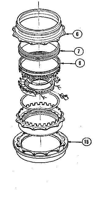
f. Install outer vane sup-
port, complete with vane assem-
bly, in inner (small) exit duct
(15), aligning grooved lugs.
3. On engines with only four
shroud segments installed, pro-
ceed as follows:
a. Select appropriate class
of shroud to match diameter of
compressor turbine (Task 2-3-1).
b. Install four segments
(8) (one long, three short) on
vane outer platform, locating
segment lugs between vane lugs.
Insure that one end of long seg-
ment aligns with top of vane sup-
port (offset hole) and the other
end runs counterclockwise when
looking at the trailing edges of
the vanes.
c. Install heat shield (7)
over segments, locate shroud
housing (6) over assembly, align
bolt holes and press into posi-
tion.
NOTE
Light tapping with soft-
face hammer is permissible
to drive housing fully
home.
GO TO NEXT PAGE
3-21