TM 55-2840-254-23
4-40 INSTALL NO. 4 AND 5 BEARING PACKAGE SEALS (AVIM) (Continued)
4-40
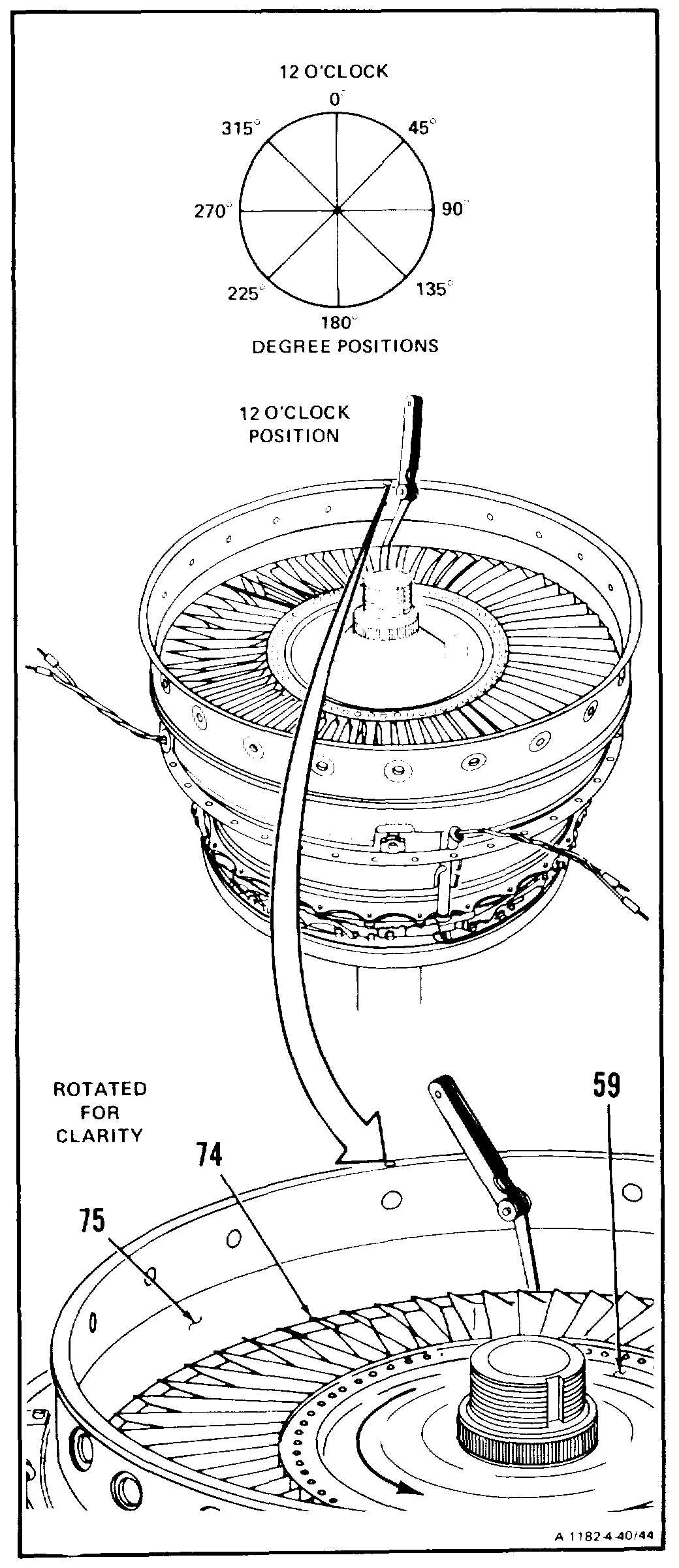
41. Measure clearance between tips of blades (74)
and fourth stage power turbine nozzle (75)
(tip clearance) at 0, 45, 90, 135, 180, 225, 270
and 315-degree positions as follows:
a. Insert thickness gage between fourth stage
power turbine nozzle (75) and blade (74)
tip. Rotate fourth stage turbine rotor (59)
counterclockwise one revolution for each
check.
b. Tip clearance shall be 0.020 inch minimum.
GO TO NEXT PAGE
4-235