TM 55-2840-254-23
4-40 INSTALL NO. 4 AND 5 BEARING PACKAGE SEALS (AVIM) (Continued)
4-40
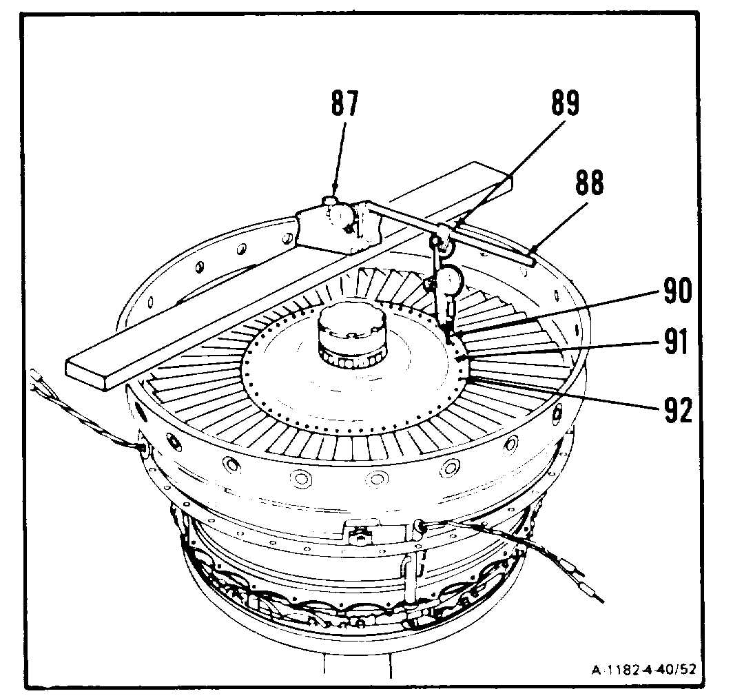
c. Adjust arm 188) at base (87) and clamp (89).
Position pointer (90) on surface (91), just
Inside of blade retaining pins (92).
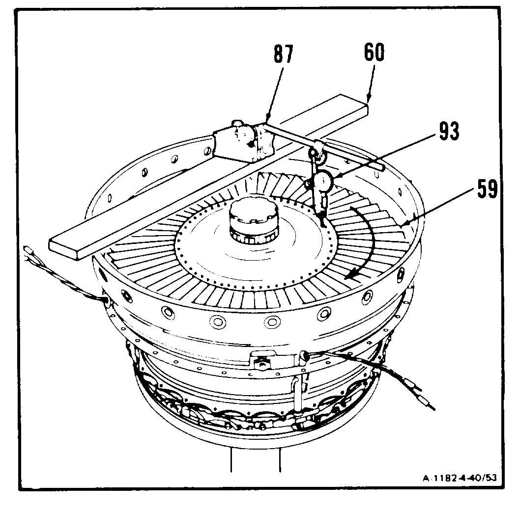
d. Zero indicator (93). Rotate fourth stage
power turbine rotor (59) clockwise while
noting Indicator reading.
e. Runout shall be no more than 0.003 inch.
NOTE
If runout is not within limits, do steps
37. through 47. If runout is still not
within limits, replace power turbine as-
sembly.
f. Remove dial indicator (87) and locating bar
(T1) (60).
GO TO NEXT PAGE
4-240