TM 55-2840-254-23
4-61
INSTALL SECOND TURBINE NOZZLE, SPACER, AND CASE (AVIM) (Continued)
4-61
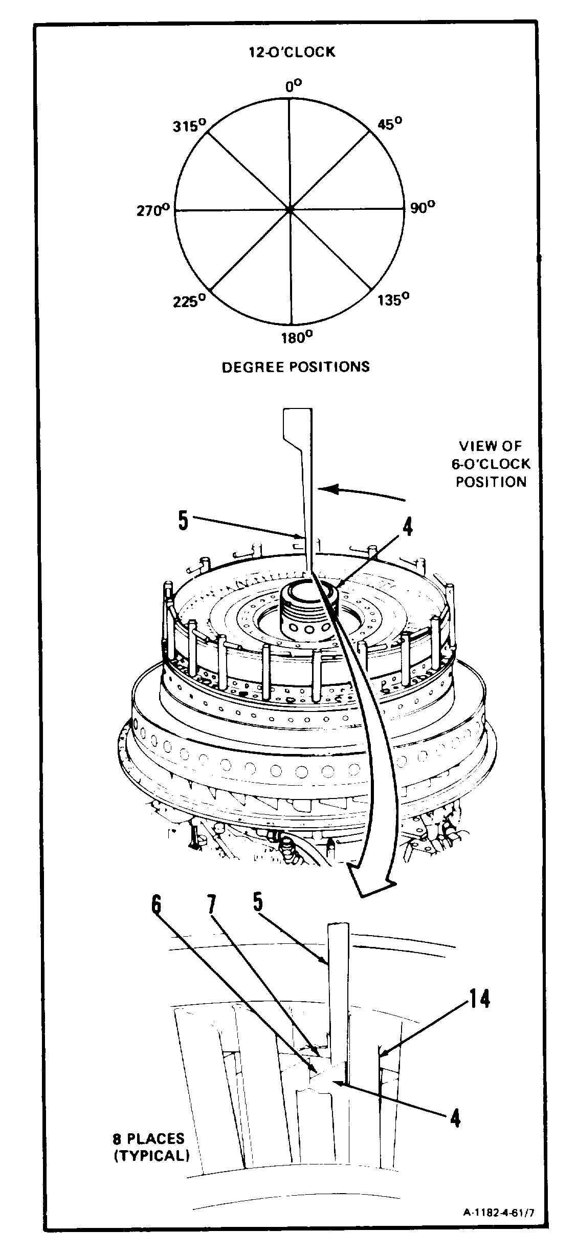
9. Measure first turbine disc assembly (4) tip clear-
ance at 0, 45, 90, 135, 180, 225, 270, and 315
degree positions as follows:
a. Insert thickness gage (Appendix E) (5) be-
tween second turbine nozzle vanes (14) and
between blade tip (6) and turbine rotor case
inside diameter (7).
b. Rotate first turbine disc assembly (4) counter-
clockwise one revolution for each check.
GO TO NEXT PAGE
4-392