TM 55-2840-254-23
4-61 INSTALL SECOND TURBINE NOZZLE, SPACER, AND CASE (AVIM) (Continued) 4-61
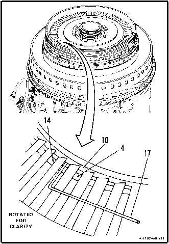
15. Check axial clearance between first turbine
disc assembly (4) and second turbine nozzle
(10). Use 0.066 inch bent wire gage (Appen-
dix E) (17) inserted through second turbine
nozzle vanes (14).
INSPECT
16. If clearance cannot be obtained recheck first
turbine rotor installation procedure.
a. Remove second turbine nozzle (Ref. Task
4-57).
b. Remove first turbine disc assembly (Ref.
Task 4-62).
c. Install first turbine disc assembly (Ref. Task
4-66). Maintain as close to minimum clear-
ance 0.100 inch between first turbine disc
assemblv and first turbine nozzle as possible.
d. Repeat steps 4. thru 16.
17. If clearance still cannot be met replace parts as
necessary.
INSPECT
FOLLOW-ON MAINTENANCE:
Install Second Turbine Disc Assembly
(Task 4-56).
Install Combustion Section and Power Turbine
(Task 3-8).
Service Engine Oil System (Task 1-74).
END OF TASK
4-395/(4-396 blank)