TM 1-1500-204-23-1
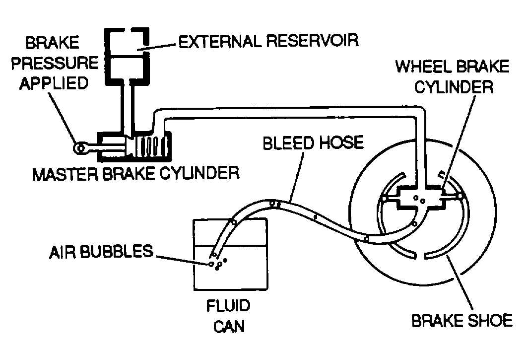
(1) Gravity method. A bleeder hose is attached
to the bleeder valve, and the free end of the hose is
placed in a receptacle containing enough hydraulic fluid
to cover the end of the hose, as shown in figure 9-11.
The air-laden fluid is then forced from the system by
operating the brake. If the brake system is a part of the
main hydraulic system, a portable hydraulic test stand
may be used to supply the pressure. If the system is an
independent master cylinder system, the master cylinder
will supply the necessary pressure. In either case, each
time the brake pedal Is released the bleeder valve must
either be closed or the bleeder hose pinched off;
otherwise, more air will be drawn back into the system.
Bleeding should continue until no more air bubbles
come through the bleeder hose into the container.
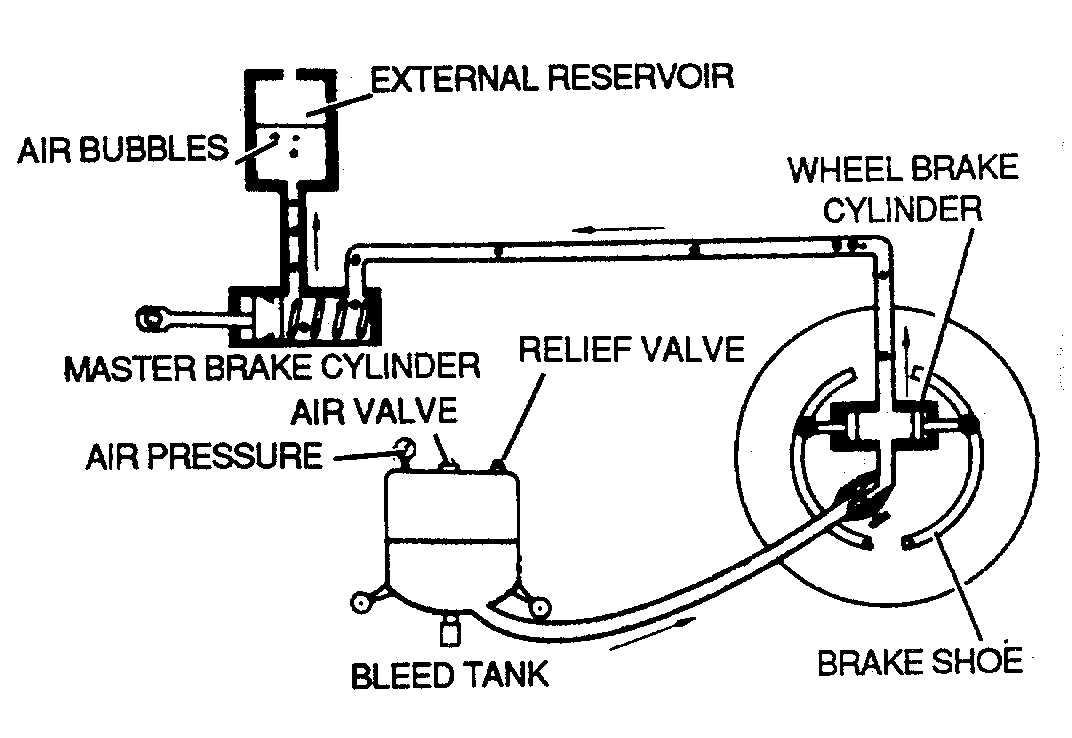
(2) Pressure method. In the pressure method,
the air is expelled through the brake system reservoir or
other specially provided location. Some aircraft have a
bleeder valve located in the upper brake line. In using
this method of bleeding, pressure is applied using a
bleed tank, as shown in figure 9-12. A bleed tank is a
portable tank containing hydraulic fluid under pressure.
The bleeder tank is equipped with an air valve, air
gauge, and a connector hose. The connector hose
attaches to the bleeder valve on the brake assembly
and is provided with a shutoff valve. Perform this
method of bleeding strictly in accordance with the
specific aircraft maintenance manual.
j.
Brake System Safety. Follow all safety
precautions given by the applicable maintenance
manual. If It is necessary to approach a wheel with a
hot brake, do so either from directly in front or directly
behind the aircraft.
Figure 9-11. Gravity Method of Bleeding Brakes
Figure 9-12. Pressure Method of Bleeding Brakes
9-8. Wheel Maintenance. Aircraft wheels are
manufactured from magnesium, aluminum, or steel
alloy. These materials are susceptible to corrosion,
scoring, and gouging. Corrosion contributes to the high
replacement rate of wheels. Paint coatings should be
maintained in good condition to prevent corrosion.
Fatigue cracks and complete wheel failure can result
from inadequate corrosion control, as well as scratches
and tool marks in critical stress areas. Care should be
taken to ensure proper usage of tools. Maintain wheels
using the following paragraphs.
a.
Wheel Cleaning. The following procedures
describe wheel cleaning.
(1) Remove
tire,
tube,
and
bearing
and
disassemble the wheel. See TM 55-2620-200-24 for
demounting procedure.
WARNING
Dry-cleaning solvent is flammable
and solvent vapors are toxic. Use P-
D-680, Type II Solvent in a well-
ventilated area. Keep away from
open flames. Avoid prolonged
solvent contact with skin.
(2) Wash demounted wheel in dry-cleaning
solvent,
Federal
Specification
P-D-680,
or
trichloroethylene, Federal Specification O-T-634.
NOTE
Bearings should be cleaned and
repacked if wheel is removed or was
submerged in water.
9-10


