TM 1-1500-204-23-2
valve device is spring-loaded to one position and solenoid-actuated to the other position.
c.
Check Valves. For hydraulic components and systems to operate as they should, the flow of fluid must
be rigidly controlled. Fluid must be made to flow according to needs of the system. Many kinds of valve units are used
for exercising such control. One of the simplest and most commonly used is the check valve. The check valve allows
free flow of fluid in one direction, but no flow or a restricted flow in the other direction. There are two types of in-line
check values simple and orifice.
(1)
Simple-type. Simple-type check valves shown in figure 4-127 are used when a free flow of fluid
is desired in only one direction. Fluid entering the inlet port of the check valve forces the valving device off its seat
against the spring. This permits fluid to flow through the passageway thus opened. The instant that fluid stops moving in
this direction, the valving device is returned to its seat by the spring. This blocks the opening in the valve seat, thus
blocking the flow of fluid through the valve.
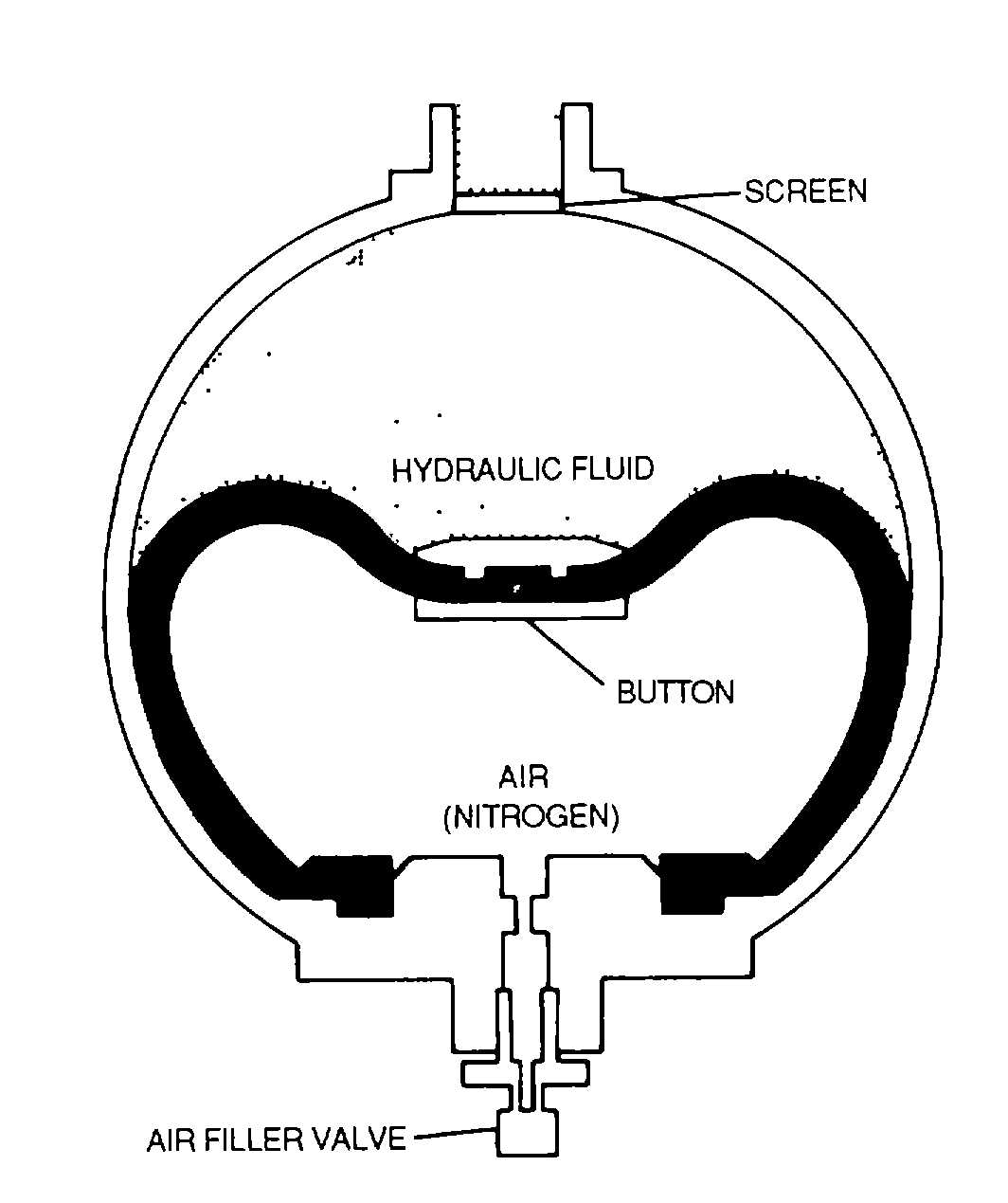
Figure 4-119. Spherical Accumulator
(2)
Orifice-type. The orifice-type check valve (sometimes called a damping valve) is used to allow
normal operating speed of a mechanism by providing free flow of fluid in one direction, while allowing limited operation
speed through restricted flow of fluid in the opposite direction. An orifice-type check valve is shown in figure 4-128. The
operation of the orifice-type check valve is the same as that of the simple-type except for the restricted flow allowed
when closed. This is accomplished by having a second opening in the valve seat. This second opening is never closed
and is the means by which some reverse flow can take place through the valve. The second opening is much smaller
than the opening in the valve seat. As a rule, this opening is a specified size in order to maintain close control over the
rate at which fluid can flow through the valve in reverse.
(3)
Marking of valves. The director of fluid flow through in-line check valves is indicated by stamped
arrow markings on the housing as shown in figures 4-127 and 4-128 On the simple-type in-line check valve, a single
arrow shows the direction in which fluid can flow. The orifice-type in-line check valve is usually marked with two arrows.
One arrow is more pronounced than the other, and indicates the direction of unrestricted flow. The other arrow is either
smaller than the first or of broken-line construction and points in the direction of restricted reverse fluid flow.
d.
Sequence Valves. The purpose of sequence valves (sometimes called timer check valves) is to set up a
sequence of operation. In Army aircraft, these valves are used in such mechanisms as landing gear doors, landing gear
uplocks and downlocks, cargo doors, ramps, and locks, and ejection seats to cause hydraulic operations to occur in a
specific order. Two major types are used: mechanically-actuated and pressure-actuated.
(1)
Mechanically-actuated sequence valves. The mechanically-actuated sequence valve is the type
commonly used in Army aircraft. A typical valve of this type (shown in figure 4-127) consists of a housing in which there
are two ports, a ball valving device, two springs, a plunger that extends through one end of the housing, and the
necessary seals to prevent leakage. The input pressure line is connected as shown to the actuating cylinder and to
sequence valve B Since sequence valve B is now closed, fluid cannot pass through it. When the door is opened, the
door actuating cylinder piston rod extends far enough to contact and depress the plunger of sequence valve B. This
opens sequence valve B and allows fluid pressure to pass through to the
4-127