TM 1-1500-204-23-4
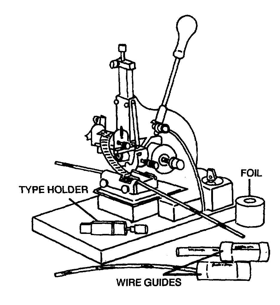
Figure 3-3. Hand Wire Marking Machine
Table 3-2. Recommended Sizes of Marking Type
Height of letters
Wire size
(Inches)
No. 26 and No. 22
1/16
No. 20 thru No. 14
5/64
No. 12 thru No. 0000 and
7/64
Coaxial Cable
(2)
Ensure
terminal
blocks
are
securely
mounted.
(3)
Ensure terminal connections to terminal
block studs, and nuts on unused studs, are tight.
(4)
Ensure
evidence
of
overheating
and
corrosion is not present on connections to terminal block
studs.
(5)
Ensure the number of terminal connections
to a terminal block stud does not exceed four.
(6)
Inspect for physical damage to studs, stud
threads, and terminal blocks. Replace cracked terminal
strips and those studs with stripped threads.
h.
Fuses and Fuse Holders. When installing fuses
and fuse holders, inspect using the following procedures:
(1)
Inspect for security of connections to fuse
holders.
(2)
Inspect for the presence of corrosion and
evidence of overheating on fuses and fuse holders.
Replace corroded fuses and clean fuse holders. If
evidence of overheating is found, check for correct rating
of fuse.
(3)
Inspect for security of mounting of fuse
holder.
(4)
Inspect for replenishment of spare fuses
used in flight. Replace with fuses of appropriate current
rating only.
(5)
Inspect for exposed fuses susceptible to
shorting. Install cover of non-conducting material if
required.
i.
Splices. When installing crimp type connectors,
inspect splices using the following procedures:
(1)
Check for the presence of snug-fitting
transparent insulating tubing extending at least 1/2 inch
over each end and tied in place with waxed cord unless
the connector is of the pre-insulated type. Use of
transparent tape is approved, but only as a temporary
means, to be replaced as soon as possible.
(2)
Check for the spacing of splices at
staggered intervals to prevent excessive enlargement of
the bundle. Groups of non-staggered splices need not be
replaced; however, it may be necessary to use extra
damps to support the added localized weight.
NOTE
·
Splices may be used within 12
inches of a termination device
when attached to the pigtail
spare
lead
of
a
potted
termination device, or to splice
multiple wires to a single wire,
or to adjust the wire sizes so
that they are compatible with
the contact crimp barrel sizes.
·
The application of splices shall
be
design
control
and
be
authorized by the applicable
technical manual or ATCOM
engineering.
Change 3
3-6


