TM 1-1500-204-23-4
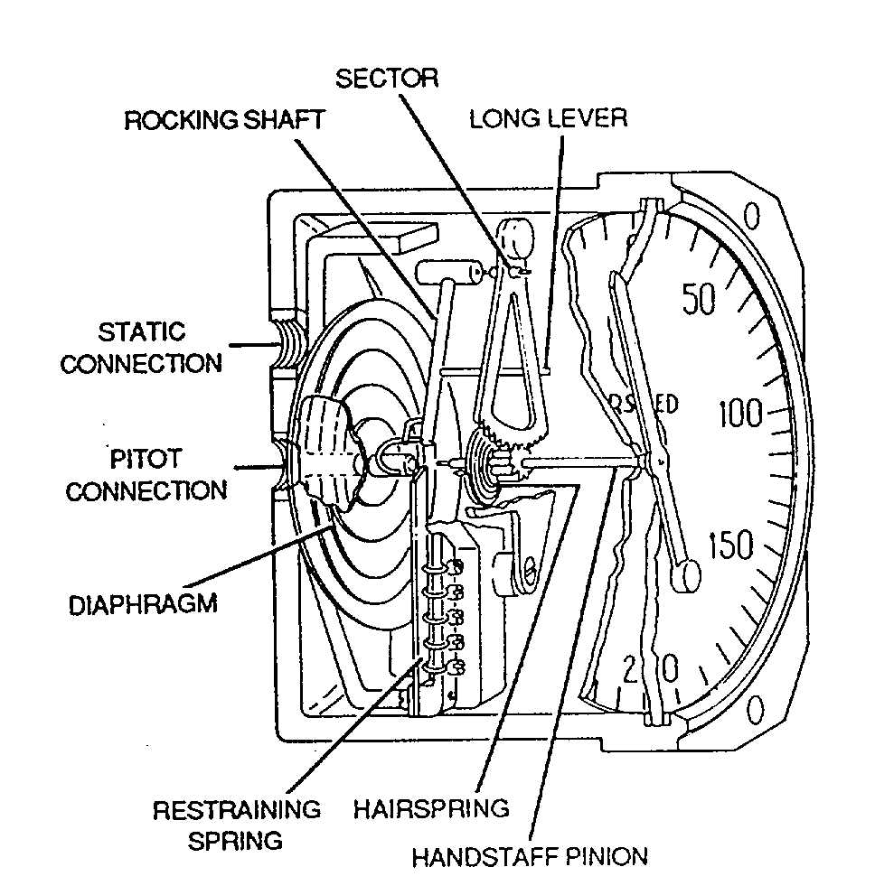
Figure 4-11. Airspeed Indicator
Movements of the capsule caused by the resulting
pressure difference are converted by mechanical
linkage to pointer movement over the calibrated dial.
The airspeed indicator face is graduated in knots.
(2) Testing. The following paragraphs
describe test procedures and replacement criteria for
airspeed indicators while installed on aircraft.
(a) Required equipment. To test the
airspeed
indicator,
use
the
following
required
equipment:
·
Pitot static system tester (The
tester must show evidence of
current calibration)
·
Adapters and fittings
·
Plugs and caps
(b)
Airspeed
indicator
test
procedures. Test using the procedures that follow:
1
Disconnect pitot static lines on
airspeed indicator.
2
Plug
lines
to
prevent
contamination.
3
Connect airspeed indicator to
pitot static system tester.
4
Compare the reading of the
installed indicator against the reading on the tester at
the test points shown in table 4-1.
NOTE
·
Tests do not need to go
higher than the rated speed of
the aircraft.
·
Gently tap indicator before
reading.
5
Perform pitot line leak test
paragraph 4-3c(2)(b).
6
Perform static line leak test
paragraph 4-3c(2)(c).
7
Disconnect pitot static system
tester.
8
Connect pitot static lines to
airspeed indicator.
(c)
Replacement
criteria.
Replacement criteria are as follows:
·
Replace airspeed indicator if it
fails to meet the tolerances in
table 4-1.
NOTE
The airspeed indicator does not
always have graduations for each
knot;
therefore,
interpret
tolerances 3, 4, and 6 to retain
rather than to replace indicator.
·
Airspeed indicators which do not
pass
the
performance
requirements shall be turned in
for overhaul.
f. Vertical Speed Indicators. Principles of
operation and testing procedures are described in the
following paragraphs.
(1) Principles of operation. The vertical
velocity indicator, as shown in figure 4-12, located on
the flight instrument panel, indicates the rate of ascent
or descent in feet per minute. The pointer moves
clockwise when indicating ascent and counterclockwise
when indicating descent. The vertical velocity indicator
incorporates two air-enclosing chambers: a pressure-
sensitive diaphragm vented directly to the static line,
and the air-tight case of the instrument vented to the
static line through a thin-walled porcelain capillary tube.
4-13


