TM 1-1500-204-23-4
2
Slowly apply pressure to pitot
line until the airspeed indicator reads normal cruising
speed. Use appropriate power supply in accordance
with pilot-static system being tested. Pinch off pressure
supply at flexible tube.
3
Tap indicator to remove friction
effects. When indicator pointer drops more than 10
miles an hour (8.7 knots) in 1 minute, a leak is indicated.
Repair faulty connections or cracks in pitot lines as
necessary.
4
Remove test apparatus from
pitot tube.
5
Remove tape from the pitot
tube drain holes.
(c) Static line leak test procedures.
Static line leak test connections are shown in figure 4-9.
Do tests using the procedures that follow:
1
Set altimeter pointers to field
elevation.
2
Tape unused static ports.
CAUTION
When applying suction to the
static line, the airspeed indicator
and computer equipment may be
damaged.
3
Slowly apply suction to static
line until airspeed indicator reaches full scale. Close
vacuum source and tap altimeter at same time until rate
of climb stabilizes at zero. After stabilization, the
altimeter should not drop more than 100 ft. in the next
minute.
4
Slowly remove suction from
static lines until altimeter reads field elevation.
5
Remove test apparatus from
static port.
6
Remove tape from static ports.
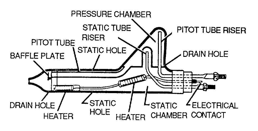
d. Pitot Static System Heater. Pitot static tubes,
as shown in figure 4-10, are provided with heaters to
prevent icing during flight. Principles of operation and
testing procedures are described in the following
paragraphs.
(1) Principles of operation. During ice-
forming conditions, pilot heat is selected by a switch in
the cockpit. Heating elements heat the pitot head to
provide pitot anti-icing.
(2) Testing. Test pitot static system heater
using the following paragraphs.
(a) Required equipment. No special
required equipment is needed.
(b) Pitot static heater test procedures.
Test using the procedures that follow:
WARNING
Exercise caution when touching
pitot tube with fingers as serious
burns may result.
1
Turn aircraft battery switch ON.
2
Turn pilot heater switch ON and
check for heat rise by touching pitot head lightly with
fingers.
3
When elements do not heat
within 2 minutes, and wiring is correct, pitot head must
be replaced.
e. Airspeed Indicators. Principles of operator and
testing procedures are described in the following
paragraphs.
(1) Principles of operation. The airspeed
indicator, as shown in figure 4-11, shows the speed of
the aircraft relative to the air mass through which it is
flying. Each instrument is a pressure-sensitive unit
actuated by the differential between impact and static air
pressures. The impact (pitot) pressure is transmitted
from the pitot head to the inside of the pressure-
sensitive diaphragm in the instrument case, while static
pressure is applied to the interior of the case.
Figure 4-10. Pitot Tube
4-12


