TM 1-1500-204-23-6
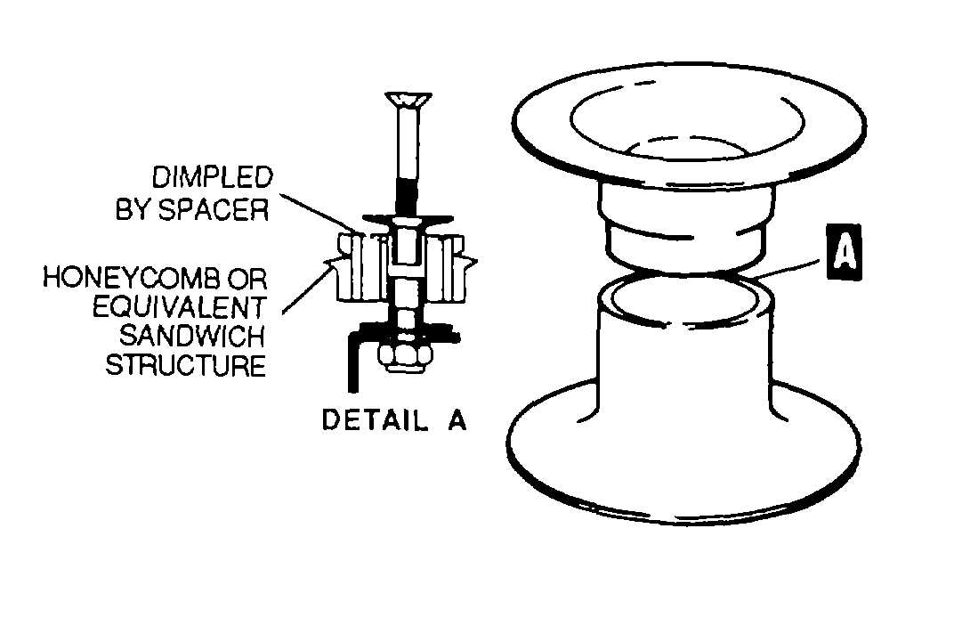
Figure 2-67. Spacer
2-13.
Tie Rods. Tie rod assemblies are used as tension carrying structure members which have a high strength and
will affect the alignment of adjacent structural elements. Tie rod assemblies consist of a high- strength steel tie rod,
fittings or terminals, and checknuts. The tie rod is threaded with right and left threads at opposite ends to allow for
adjustment. A portion of the shank is flat, for a wrench to be used to turn the tie rod during installation and adjustment.
A checknut and fitting are installed on each end of the tie rod. Checknuts are tightened against the fittings to prevent
loosening by vibration.
a.
Identification. Round and square tie rods, AN701 through AN708, are shown in figure 2-70. The round and
square tie rods are used internally for various bracking purposes where a light, strong, adjustable member is
required.
b.
Tie Rod Terminal Fittings. There are several different types of tie rod terminal fittings. The most common Is
AN665. This fitting has a clevis end, and is threaded for attachment to the threaded ends of the tie rod shank.
After adjusting tie rod to desired tension, tighten checknut and insert a wire through drilled hole In the terminal.
If the wire passes through the terminal, the tie rod shank is not screwed into fitting far enough. This terminal Is
Identified in figure 2-71.
2-14.
Turnbuckles. Turnbuckle bodies are barrel- shaped, with each end threaded internally, one end with right-
hand threads, the other having left-hand threads. Various turnbuckles are identified in figure 2-72. Turnbuckle
assemblies are used to maintain control system cable tension. Earlier assemblies used AN 155 turnbuckle body, AN 170
cable eyes, AN 162 forks, and other AN parts. However, the AN series has been superseded by the MS series, but the
AN parts should be used until existing stocks are depleted. Current turnbuckle assemblies are made up of MS21251
body, MS21255 cable eyes, MS21252 clevis rod ends, and other MS parts as needed.
a.
Turnbuckle Installation. When installing cable system turnbuckles, screw both threaded terminals an equal
distance Into barrel. All terminals must be screwed into the barrel far enough that no more than three terminal
threads or four barrel threads are exposed on initial installation of a cable assembly. These limits are shown in
figure 2-73. The maximum of four exposed barrel threads applies only to the initial installation of the cable so
that If the cable stretches, the turnbuckle can be adjusted to the desired cable tension, at which time more or
less than four barrel threads may be exposed. AN series turnbuckles are lockwired as follows:
(1) Adjust turnbuckle to Its locking position.
(2) Pass two locking wires through the center of the turnbuckle barrel.
(3) Bend the ends of the wires 90 degrees toward the ends of the turnbuckle barrel.
(4) Pass the wire ends through the hole in the turnbuckle eyes between the jaws of the turnbuckle fork.
(5) Bend the wires back toward the center of the turnbuckle and wrap four times around the shank.
(6) When a swaged terminal Is being lockwired, one wire is passed through the hole provided for In the
terminal, looped over the free end of the other wire and both ends wrapped four times around the
shank.
(7) MS series turnbuckles are locked with MS21256 locking clip MS21251 turnbuckle bodies are slotted
internally to accept the MS21256 locking clip.
b.
Turnbuckle Inspection. Replace turnbuckles, cable terminals, and clevis found through visual inspection to be
cracked, scratched, nicked, dented, bent, distorted, corroded, or have stripped threads. Minor nicks,
scratches, or corrosion pits less than 0.005 inch deep may be removed by cleaning and burnishing smooth to
restore the part to serviceable status.
2-67