
NAVAIR 01-1A-505-2
003 02
TO 00-25-255-1
Page 5
TM 1-1500-323-24-2
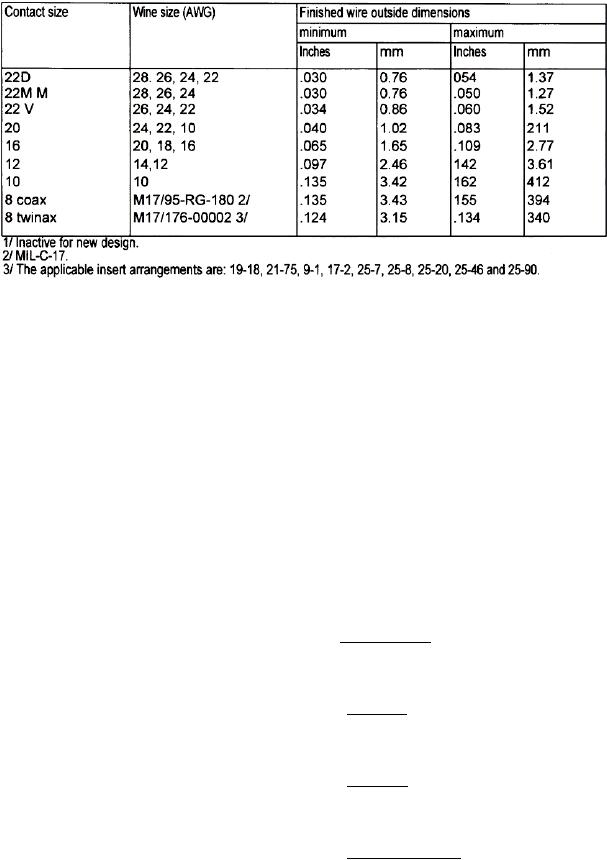
Table 1. Wire Sizes and Diameters
b. All series are designed to ensure proper
6. MATING SEAL. Plugs and receptacles with pin
orientation of the mating halves prior to closure.
inserts have a resilient face with individual pin barriers
so as to seal against the hard face socket insert. The
resilient interface seal provides individual contact seals
c. All series include hermetically sealed
in the mated condition between each contact and the
receptacles with fixed solder contacts.
shell. Series I, II, and III are provided with a peripheral
seal, and Series IV incorporates an o-ring seal.
d.
All series include EMI shielding.
7. SHELL. Shells, including mounting flanges, are of
e. Series I, III, and IV provide electrical
one piece construction and designed to retain their
continuity between mated shells prior to contact
inserts in one position by a mechanical means. Each
engagement with the contacts so located as to be
plug and receptacle has at least one blue color band,
protected from handling damage and inadvertent
which indicates rear release retention system, located
electrical contact (scoop proof).
so as to be readily visible.
f. S e r i e s I I p r o v i d e l o w s i l h o u e t t e f o r
8. COUPLING. Connectors shall be capable of being
minimum size and weight.
fully coupled and uncoupled without the use of tools.
9. Series I and II. A detent is provided in the coupling
4. WIRE SEALING. Wire sealing is accomplished by
mechanism so that an audible click is heard when
the use of a grommet seal designed to seal against the
proper coupling is complete.
inserted wire outside diameter. The outer diameter
shall be within the applicable size range as specified
10. Series III. Complete coupling is accomplished by
(Table 1).
clockwise rotation of 360 of the coupling nut to
provide metal to metal contact.
NOTE
11. Series IV. Complete coupling is accomplished by
All unwired contacts shall have sealing plugs
a clockwise rotation of 90 to a detent and provides an
installed.
audible click and an indication is felt.
5. GROMMET SEALING PLUGS. The grommets of
12. Visual Indication. On Series I and II, provision will
environment resistant connectors are designed to
be made for visual determination of complete
accept sealing plugs in accordance with MS27488 to
coupling. On Series III and IV, a red band is visible
be used where unwired contacts are placed. The
when not mated and not visible when fully mated.
connector when ordered as a unit, will have sealing
plugs enclosed so as to equal 10% of the number of
contacts but not less than one.