
NAVAIR 01-1A-505-2
003 02
TO 00-25-255-1
Page 8
TM 1-1500-323-24-2
Figure 1. MIL-DTL-38999 Connectors (Sheet 2 of 2)
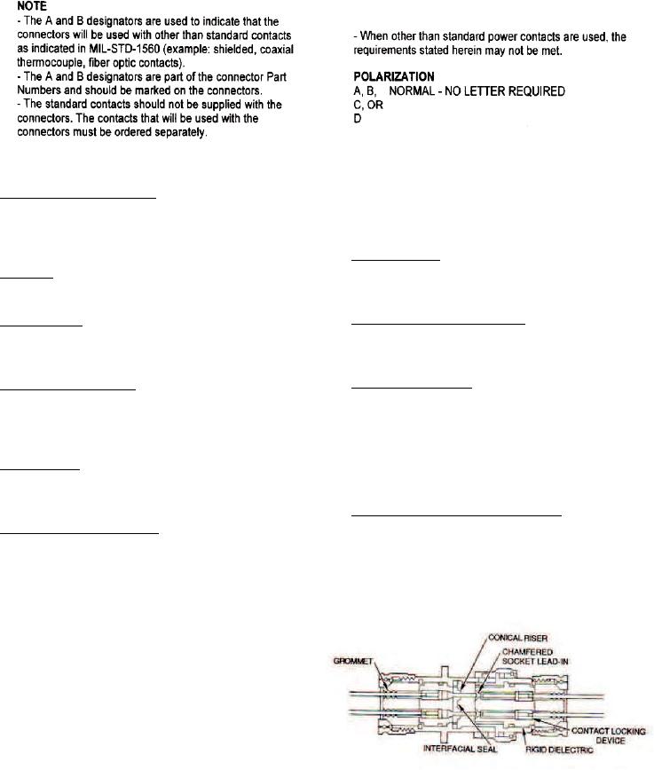
30. Contact Locking Device. The contact locking
38. CONTACTS. Contacts may be fixed or crimp
devices are contained in the rigid dielectric and
removable.
securely hold the contacts during normal coupling
(Figure 2).
39. Fixed Contacts. Contacts in hermetically sealed or
through-bulkhead receptacle are fixed, non-removable
31. Rotation. The inserts are secured in a manner so
and solder-able, or feed through.
as to prevent rotation or movement.
40. Crimp Removable Contacts. Crimp removable
32. Interface Seal. All pin contact inserts will have a
contacts may be used with all environment resisting
resilient interface seal bonded to the front face to
classes of connectors.
prevent water intrusion.
41. Contact Availability. Crimp contacts are supplied
33. Hermetic Receptacles. A vitreous or glass-like
with each connector unit package and consist of a full
material is used to insulate and seal the contacts and
compliment plus 1 spare per size for connectors of 26
all pin contacts will have an interface seal. The contacts
contacts or less and those connectors with more than
are not removable.
26 contacts will have 2 spares of each size used.
Contacts may also be ordered in individual quantities
34. Conical Riser. The conical riser is a raised portion
when necessary.
of the interface seal around each contact which ensures
sealing.
42. Installation and Removal Tools. The proper
installation and removal tools must be used to
35. Chamfered Socket Lead-In. The chamfered socket
assemble or disassemble the connector. The connector
lead-in aids in coupling, allowing the pins to line up
when ordered as a unit package will include one MIL-
with the socket. They also aid in sealing the pin to the
I-81969/14-XX tool.
conical riser of the socket.
36. INSERT ARRANGEMENTS. The insert
arrangement is the number and size of the contacts
available by shell size (Table 2).
37. INSERT CONFIGURATION. The insert
configuration is the manner in which the contacts are
placed within the insert in a standard configuration.
All arrangements identified in Table 2 are illustrated
(Figure 3). The connector's service rating shows the
connectors' maximum operating voltage (Table 3).
Figure 2. Construction