
NAVAIR 01-1A-505-2
004 02
TO 00-25-255-1
Page 29
TM 1-1500-323-24-2
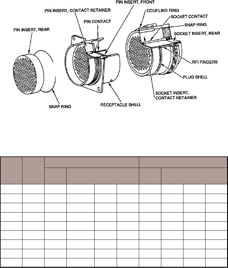
Figure 23. MIL-C-81511 Design Features
Table 11. MIL-C-81511, Series 4 Power Contact Application
Socket Contacts
Pin Contacts
Wire
Contact
Gage
Color Bands
Color Bands
Size
(AWG)
M39029/
M39029/
1
2
3
1
2
3
23
28-32
16-166
BN
BL
BL
18-176
BN
VI
BL
23
22-28
16-167
BN
BL
VI
18-177
BN
VI
VI
23
28-32
22-190
BN
WH
BK
-----
-----
-----
-----
23
22-28
22-191
BN
WH
BN
-----
-----
-----
-----
20
20-24
16-168
BN
BL
GY
18-178
BN
VI
GY
20
20-24
22-192
BN
WH
RD
-----
-----
-----
-----
16
16-20
16-169
BN
BL
WH
18-179
BN
VI
WH
16
16-20
22-193
BN
WH
OR
-----
-----
-----
-----
12
12-14
16-170
BN
VI
BK
18-180
BN
GY
BK