NAVAIR 01-1A-505-2
007 02
TO 00-25-255-1
Page 44
TM 1-1500-323-24-2
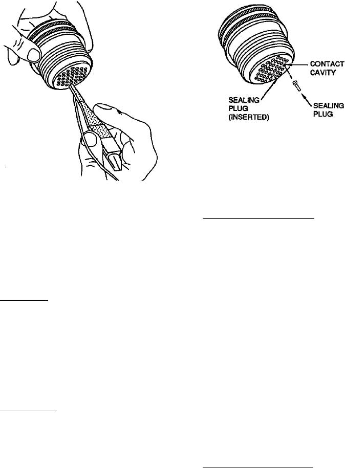
Figure 12. Contact and Sealing Plug Insertion
Figure 11. Contact Insertion
g. Pull tool straight out of contact cavity. Remove
56. Crimp Front Release Contacts. Remove wired,
tool from wire. Pull back lightly on wire to ensure
unwired, and broken wire contacts in accordance with
contact is properly seated.
following procedure:
h. Seal connector as required (Paragraph 52) and
a.
Select correct removal tool (Table 5).
install backshell.
b. If contact is unwired, remove sealing plug
52. CONNECTOR SEALING.
from cavity of contact to be removed.
53. Sealing Plugs. Seal connector in accordance with
c.
Working from the front (mating end) of
following procedure:
connector, slide hollow end of removal tool over contact
(Figure 13).
a. Fill all unused cavities with un-crimped
contacts (Paragraph 51).
d. Holding removal tool at right angle to front
insert face, push tool straight toward rear of connector,
b. Insert sealing plug, large diameter first, until
firmly pressing tool to positive stop when tool bottoms
bottomed in contact cavity. Do not insert further than
in insert cavity.
knob. Fill all cavities that have un-crimped contacts
(Figure 12). Preserve connector in accordance with
e.
Maintain pressure on tool handle and slide
NAVAIR 01-1A-505-1, WP 026 00.
collar of tool forward until it stops. Contact will be
partially ejected from rear of connector insert.
54. Moisture Barrier. For connector sealing procedures,
including application of sealant to grommet sealed
f.
Remove tool by pulling straight back to clear
connectors, refer to NAVAIR 01-1A-505-1, WP 025 00.
connector insert face. Remove contact out rear of
connector by pulling lightly on wire or using a mating
55. CONTACT REMOVAL. The following paragraphs
contact to push out released contact.
give contact removal procedures for front release and
rear release crimp contacts.
57. Crimp Rear Release Contacts. Remove wired,
unwired, and broken wire contacts in accordance with
following paragraphs.

