
NAVAIR 01-1A-505-2
010 02
TO 00-25-255-1
Page 26
TM 1-1500-323-24-2
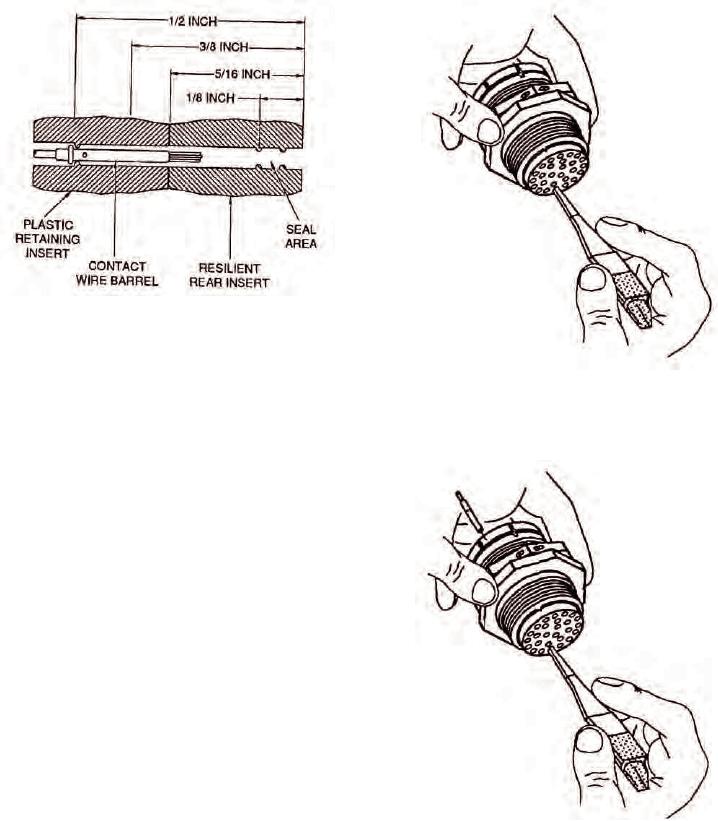
Figure 26. Typical Connector Dimensions
NOTE
Figure 27. Unlocking Contact Retention
Rotating removal tool works splayed wire
Mechanism of Broken Wire
strands into slot of tool, allowing tool to pass.
Removal tool may be blocked at rear of contact
by plastic insert or additional strands of broken
wire.
e.
If resistance is felt before removal too] reaches
back end of contact, withdraw too] slightly, rotate
about 1/6 of a turn, and reinsert tool. Repeat rotating and
insertion procedure until tool passes with minimum
additional force to 5/16 inch depth back end of contact
(Figure 27).
f.
Wiggle removal tool gently to help it into
insert bore and over back of contact. Additional rotation
may be required if broken strands are encountered.
g. Continue insertion of removal tool until
positive stop is felt at about 1/2 inch depth.
h. Exert axial pressure on engaging end of contact,
using appropriate pin or socket as pusher. If contact
does not move, seat removal tool more firmly.
i.
Push contact completely out rear of connector
Figure 28. Broken Wire Contact Removal
before disengaging removal tool (Figure 28).