
NAVAIR 01-1A-505-2
011 03
TO 00-25-255-1
Page 4
TM 1-1500-323-24-2
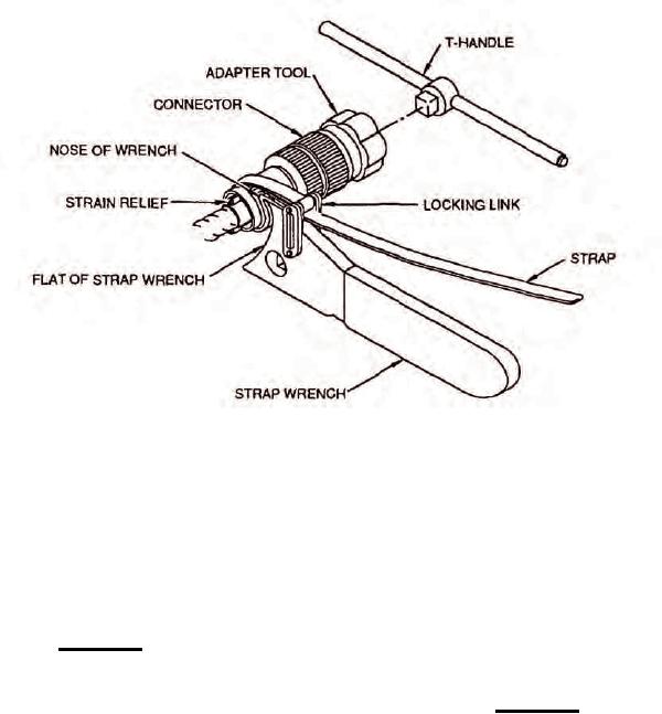
Figure 3. Starp Wrench setup and Adjustment
9. BACKSHELL REMOVAL. Backshells are used to
10.
BACKSHELL INSTALLATION. Upon
protect, shield, and add strength to connectors. When
completion of maintenance or modification (NAVAIR
modification or repair to the connector is necessary the
01-1A-505-1), the backshell must be replaced. Proceed
backshell must be removed. Proceed using following
using following procedure:
procedure:
a. Un-tape/acquire backshell from the bundle to
a. Select the correct adapter tool (Table 1) by
which it was secured temporarily. Start backshell on to
shell size, T-handle, and strap wrench (Figure 2).
connector by hand to prevent cross-threading.
CAUTION
b. Select the correct adapter tool (Table 1), T-
handle, and strap wrench (Figure 2).
Ensure white dot on adapter tool aligns with
master key of connector. Spinning tool on
CAUTION
connector will cause damage to tool and/or
connector (Figure 3).
Ensure white dot on adapter tool aligns with
master key of connector. Spinning tool on
b. Mate adapter tool to connector. Ensure white
connector will cause damage to tool and/or
dot on adapter tool aligns with master key of connector
connector (Figure 3).
(Figure 3).
c.
Mate adapter tool to connector. Ensure white
c.
Install strap wrench around part to be removed.
dot on adapter tool aligns with master key of connector
Draw strap tightly through locking link. Backshell will
(Figure 3).
rest on nose of wrench (Figure 3).
d. Install strap wrench around part to be installed.
d. Insert T-handle into socket of adapter tool
Draw strap tightly through locking link. Backshell will
(Figure 3).
rest on nose of wrench (Figure 3).
e.
To
loosen
backshell
apply
force
e.
Insert T-handle into socket of adapter tool to
counterclockwise as viewed from connector rear
provide holding (Figure 3).
(Figure 4).
f.
To tighten backshell apply force clockwise as
f.
Secure/tape backshell to bundle to prevent
viewed from connector rear (Figure 5).
loss.