
NAVAIR 01-1A-505-3
TO 1-1A-14-3
TM 1-1500-323-24-3
007 02
1 September 2011
Page 25
a.
Select correct crimp tool (Table 5 or 8).
b. Perform die closure check, install positioner,
and set selector knob for gage of wire.
Present metal tooling in some instances has
damaged the wire sealing grommet at the end
c. Insert stripped wire into contact conductor
of the connectors.
barrel. Ensure all wire strands are inside contact
conductor barrel and visible in contact inspection hole
Caution should be exercised in the use of
(Figure 12).
tooling. Inspect tips of metal tools for
distortion of probe before use as connector
damage can occur.
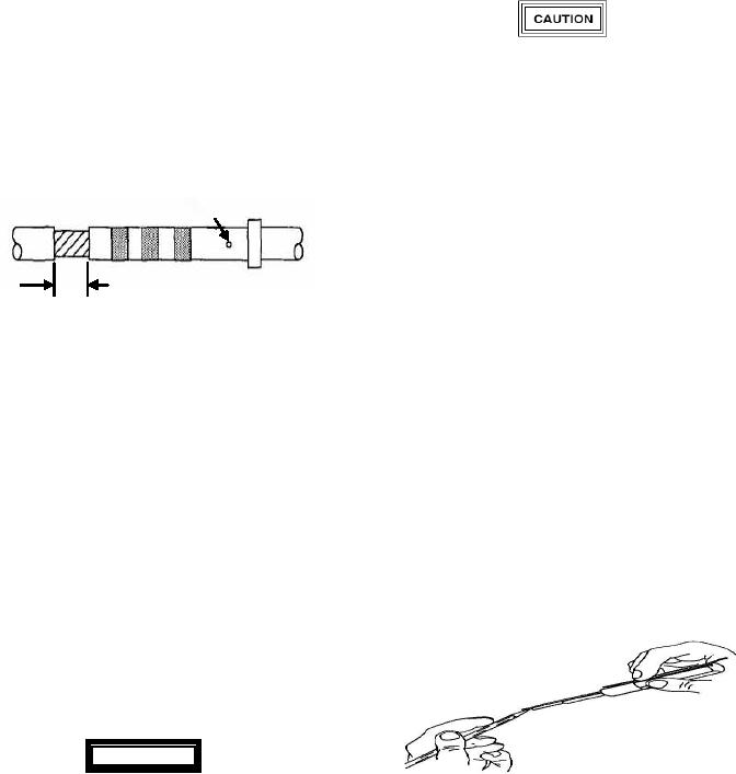
Co nta ct I nspectio n Ho le
d. Place wire and contact assembly into tip of
insertion tool (Figure 13). Ensure tool tip is over
conductor barrel and butted against contact shoulder.
Insulation Gap
e. Insert tip of contact into cavity. Start contact
1/32 Inch Min 1/16
insertion near connector center cavities and work
outward.
Figure 12. Insulation Gap
f.
Axially align contact with contact cavity.
d. If insulation gap is too large, trim conductor
as required. If insulation gap is too small, trim
g. With firm even pressure, press tool against
insulation as required.
contact shoulder and seat contact in cavity (Figure 14).
A slight click may be heard as retention tines snap into
e. Crimp contact to wire.
place behind contact shoulder.
h. Pull tool straight out of contact cavity.
75. CONTACT INSERTION. Insert wired or
Remove tool from wire. Pull back lightly on wire to
unwired contacts in accordance with following
ensure contact is properly seated.
procedure:
i.
Seal connector as required (paragraph 88).
a. Remove sealing plug and/or contact from
contact cavity (Paragraph 91).
b. Ensure wire or cable on contact is routed
through connector backshell.
c.
Select correct insertion tool (Table 5 or 8).
WARNING
Metal tool tips are sharp and can cause injury
Figure 13. Inserting Contact into Insertion Tool
to personnel and/or damage to connectors.
(Typical)