
NAVAIR 01-1A-505-3
TO 1-1A-14-3
TM 1-1500-323-24-3
008 02
1 September 2011
Page 21
NOTE
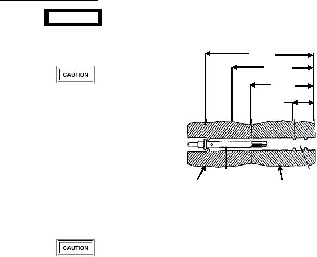
53. Broken Wire Contact Removal.
Refer to figure 19 for approximate
dimensions of a size 22 contact and cavity.
WARNING
The dimensions in this procedure are based on
a size 22 contact.
Metal tool tips are sharp and cause injury to
personnel and/or damage to connectors.
1/2 Inch
3/8 Inch
5/16 Inch
Present metal tooling in some instances has
1/8 Inch
damaged the wire sealing grommet at the end
of the connectors. Plastic tools are preferred.
Caution should be exercised in the use of
tooling.
Inspect tips of metal tools for distortion of
probe before use as connector damage can
Contact Wire Barrel
occur.
Seal Area
Resilient Rear
Plastic Retainin g
Insert
a.
Select correct removal tool (Table 4, 6 or 7).
Insert
b. Insert tip of removal tool about l/8 inch into
Figure 19. Typical Connector Dimensions
cavity at rear of connector.
c. Gently insert removal tool into cavity in about
1/16 inch units, releasing tool after each unit if resistance
is felt.
Wire strands may be encountered at any point
NOTE
up to 5/16 inch of tool insertion. It is
important not to jam any strands of wire up to
Rotating removal tool works splayed wire
this point.
strands into slot of tool, allowing tool to pass.
Withdraw removal tool anytime during
Removal tool may be blocked at rear of
insertion when it cannot be advanced into
contact by plastic insert or additional strands
connector using these procedures. Inspect tool
of broken wire.
tip for nicks, cracks, mushrooming, and other
damage that will prevent is functioning.
d. If resistance is felt before removal tool reaches
Replace removal tool and repeat procedure, if
back end of contact, withdraw tool slightly, rotate about
required.
l/6 of a turn, and reinsert tool. Repeat rotating and
insertion procedure until tool passes with minimum
additional force to 5/16-inch depth back end of contact
(Figure 19 and 20).