
NAVAIR 01-1A-505-3
TO 1-1A-14-3
TM 1-1500-323-24-3
008 02
1 September 2011
Page 17
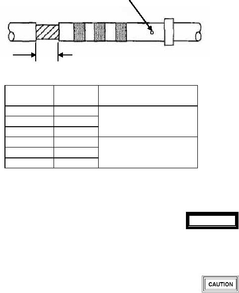
Contact Inspection Hole
Insulation Gap
Contact
Wire
Insulation
Size
AWG
Gap
22
24
1/32 Inch MIN.
22
1/16 Inch MAX.
20
20
16
20
11/32 Inch MIN.
16
5/64 Inch MAX
12
12
Figure 9. Insulation Gap
WARNING
d. If insulation gap is too large, trim conductor as
required. If insulation gap is too small, trim insulation as
required.
Metal tool tips are sharp and can cause injury to
personnel and/or damage to connectors.
e.
Crimp contact to wire.
46. CONTACT INSERTION. Insert wired or unwired
contacts in accordance with following procedure:
a. Remove sealing plug and/or contact from contact
Present metal tooling in some instances has
cavity (Paragraph 50).
damaged the wire sealing grommet at the end of
the connectors. Plastic tools are preferred.
b. Ensure wire or cable on contact is routed through
connector backshell.
Caution should be exercised in the use of
tooling.
c. Select correct insertion tool (Table 4, 6 or 7).
Inspect tips of metal tools for distortion of
probe before use as connector damage can
occur.
e. Insert tip of contact into cavity. Start contact
insertion near connector center cavities and work
outward.