
NAVAIR 01-1A-505-3
TO 1-1A-14-3
TM 1-1500-323-24-3
009 02
1 September 2011
Page 6
14. INSERT ARRANGEMENT. The insert
16. CONTACTS. Contacts are fixed, non-
arrangement is the number and size of contacts
removable, and solderable.
available by shell size (Table 1).
17. BACKSHELL REMOVAL AND
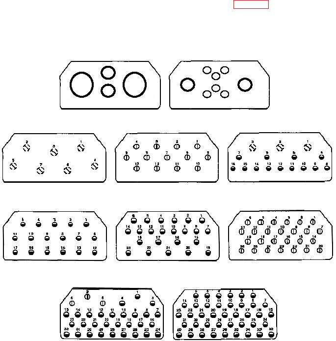
15. INSERT CONFIGURATION. The insert
INSTALLATION. For backshell removal and
configuration is the manner in which contacts are
installation refer to WP 009 03.
placed within insert in a standard configuration. All
arrangements identified in Table 1 are illustrated
(Figure 2).
C
A
B
B
D
A
H
D
F
C
G
E
004A
008A
007C
013A
016C
017A
023A
026A
032A
040A
Figure 2. MIL-DTL-21617 Insert Configurations