
NAVAIR 01-1A-505-3
TO 1-1A-14-3
TM 1-1500-323-24-3
009 02
1 September 2011
Page 9
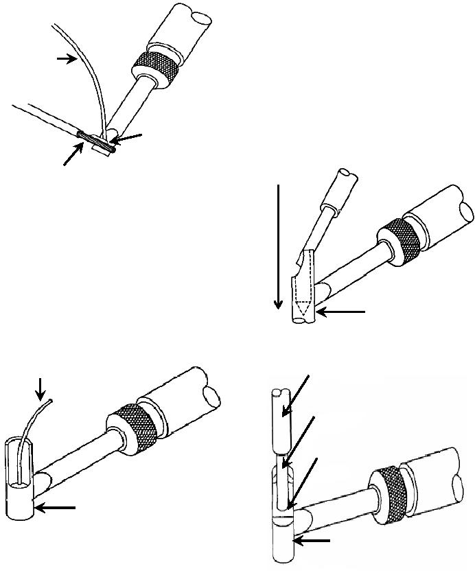
d. While maintaining contact solder cup at
soldering temperature, insert wire into contact solder
cup and slide heat source to base of contact solder cup
(Figure 8).
e. Ensure wire is bottomed in contact before
Solder
soldering iron is removed (Figure 9).
f. After solder cools, it shall form a fillet
extending from conductor to tip of solder cup (Figure
10).
Tin Wire For
Slide Soldering
One-Half
Iron Down
Stripped
When Wire Is
Stripped End
Inserted
Figure 6. Tinning Wire using Soldering Iron
24. SOLDERING HOLLOW CUP
CYLINDRICAL CONTACT.
a. Position connector at an angle with the open
end of cup toward the technician. Ensure wire to be
soldered is routed through connector backshell.
Contact Solder Cup
b. Direct soldering iron at contact solder cup
until solder flows (Figure 7).
Figure 8. Inserting wire into Solder
Solder
Insulation
Wire
Solder
Contact Solder Cup
Contact Solder
Figure 7. Filling Solder Cup with Solder
c. Pre-fill contact solder cup with enough solder
to ensure that total of pre-filled solder and pre-tinned
Figure 9. Wire Inserted into Contact
wire will fill cup without overflowing when wire is
inserted.