
TM 1-1510-262-10
SECTION XIV. FLIGHT INSTRUMENTS
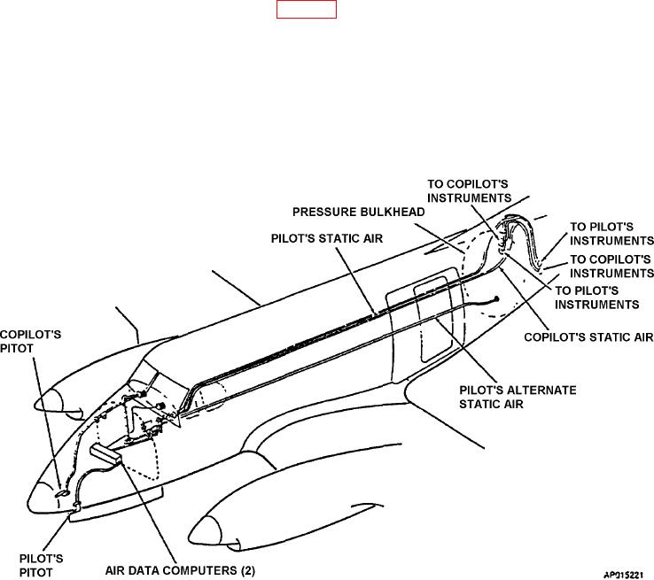
2-82. PITOT AND STATIC SYSTEM.
a. Description. The pitot and static system (Fig. 2-40) provides static pressure for pilot and copilot s light in-
formation display systems to the PFD s via the air data computers. This system consists of two pitot masts (one
located on each side of the lower portion of the nose), static air pressure ports in the aircraft s exterior skin on each
side of the aft fuselage, and associated system plumbing. The pitot mast is protected from ice formation by internal
electric heating elements.
b. Alternate Static Air Source. An alternate static air line, which terminates just aft of the rear pressure bulk-
head, provides a source of static air for the pilot s instruments, in the event of source failure from the pilot s static air
line. A control on the pilot s subpanel placarded PILOTS STATIC AIR SOURCE, may be actuated to select either
the NORMAL or ALTERNATE air source by a two position selector valve. The valve is secured in the NORMAL
position by a spring clip.
Figure 2-40. Pitot and Static System
2-83. TURN-AND-SLIP INDICATORS.
Turn-and-slip indicators are incorporated separately on the pilot and copilot Primary Flight Display (PFD). The turn
indicator is located just above the heading tape on the display screen and is labeled 2 MIN TURN . See the Original
Equipment Manufacturer (OEM) s operator manual (UNS-1F and EFI-890R) for description and operation of this in-
dicator. The slip indicator is mounted on the bezel ring of the PFD s. The slip indicator provides yaw trim information
for slip, coordinated light/turn, or skid condition.
2-84. AIRSPEED INDICATORS.
Airspeed indicator tapes are displayed on the pilot and copilot PFD s. The indicator tapes are calibrated in knots
from 40 to 300. A striped section automatically displays the maximum allowable airspeed at the aircraft s present
altitude. See the OEM s operator manual (EFI-890R) for description and operation of these indicators