TM 1-1520-264-23
Change 1 2-38.5
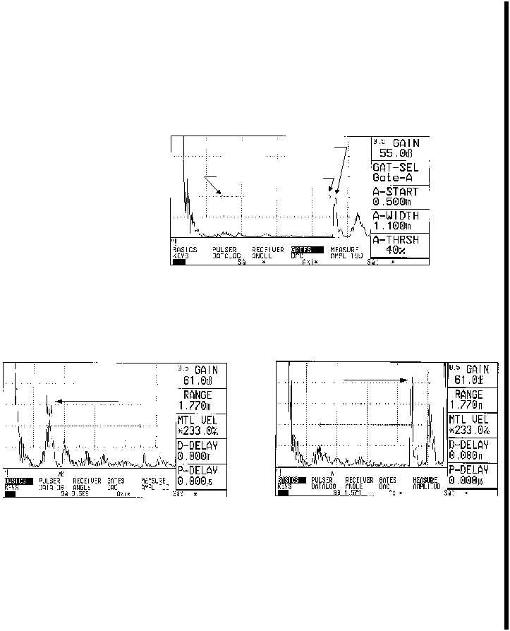
(d) Rotate the positioner away from the upper OD EDM notch, and
note the position along the time base line of the signal received
from the thread run- out groove. This signal is located just outside
the gate on the right hand side of the CRT. Moisten a finger with
couplant and damp this
signal to gain familiarity. The
appearance and amplitude of this signal is dependent upon the
radius of the thread run-out groove. A large signal will be generated
from a sharper edge, as a lesser or nonexistent signal would be
indicative of a smoother transition area. Reference Figure 5.
Figure 5. Signal from thread run-out groove
(e) Again rotate the POSITIONER 360 degrees to confirm the
electronic gate positioning and verify the upper and lower OD
EDM notches break the gate threshold. Referenc e Figure 6 for CRT
displays of upper and lower outside diameter EDM
notches.
Figure 6a. Upper OD EDM notch
Figure 6b. Lower OD EDM notch
(f) Perform the OD inspection scan after completion of the OD calibration.
Make two complete revolutions with the transducer in the OD position.
(g) Upon completion of the OD scan, wipe the calibration standard clean,
reapply couplant, and place the positioner on the calibration standard.
(h) Place the transducer in the ID guide hole. Rotate the POSITIONER, and
identify the signal obtained from the upper ID EDM notch.
Gate
Thread run-out
Gate
Upper OD
Lower OD