TM 1-1520-264-23
2-38.6 Change 1
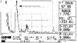
(i) Continue the rotation of the POSITIONER to locate the lower ID EDM
notch. Adjust the gain to achieve a signal height of 60% FSH. Rotate the
transducer carefully to minimize base line noise if necessary. Tighten the
set screw.
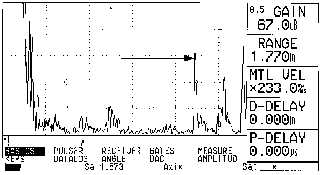
(j) Rotate the POSITIONER 360 degrees to verify both upper and lower ID signals
are readily identifiable and break the gate threshold. Reference Figure 7 for
upper and lower ID EDM notch displays.
Figure 7a. Upper ID notch
Figure 7b. Lower ID notch
(3)INSPECTION PROCEDURE
(a) Perform the OD inspection scan after completion of the OD
calibration. Make two complete revolutions with the transducer in
the OD position.
(b) Perform the ID inspection scan after completion of the ID calibration
procedure. Make two complete revolutions with the transducer in the
ID position.
(c) Perform the calibration set up every time prior to inspecting the ID or
OD of a new bolt.
NOTE
The thin couplant layer is only adequate for approximately two passes
without signal amplitude loss. Excessive couplant under the positioner can
also create noise and erroneous signals on the CRT. When in doubt clean
the bolt, reapply couplant, and rescan.
(4) ACCEPTANCE/REJECTION CRITERIA
Relevant signals exceeding the 40% gate threshold are rejectable. ID
or OD cracks can appear anywhere within the gated area. Cracks may
be detected on both the ID and OD surfaces with either scan. The
signal received from a small crack will usually have a very quick rise
and fall time when scanning. A legitimate crack indication will have a
consistent location on the bolt perimeter and can be easily repeated on
subsequent rescans. Verify all indications by cleaning the bolt,
reapplying couplant and rescanning.
(5) POST CLEAN
Clean the bolt with a cloth dampened with water to remove couplant
residue.
Lower ID
Upper ID