TM 1-1520-264-23
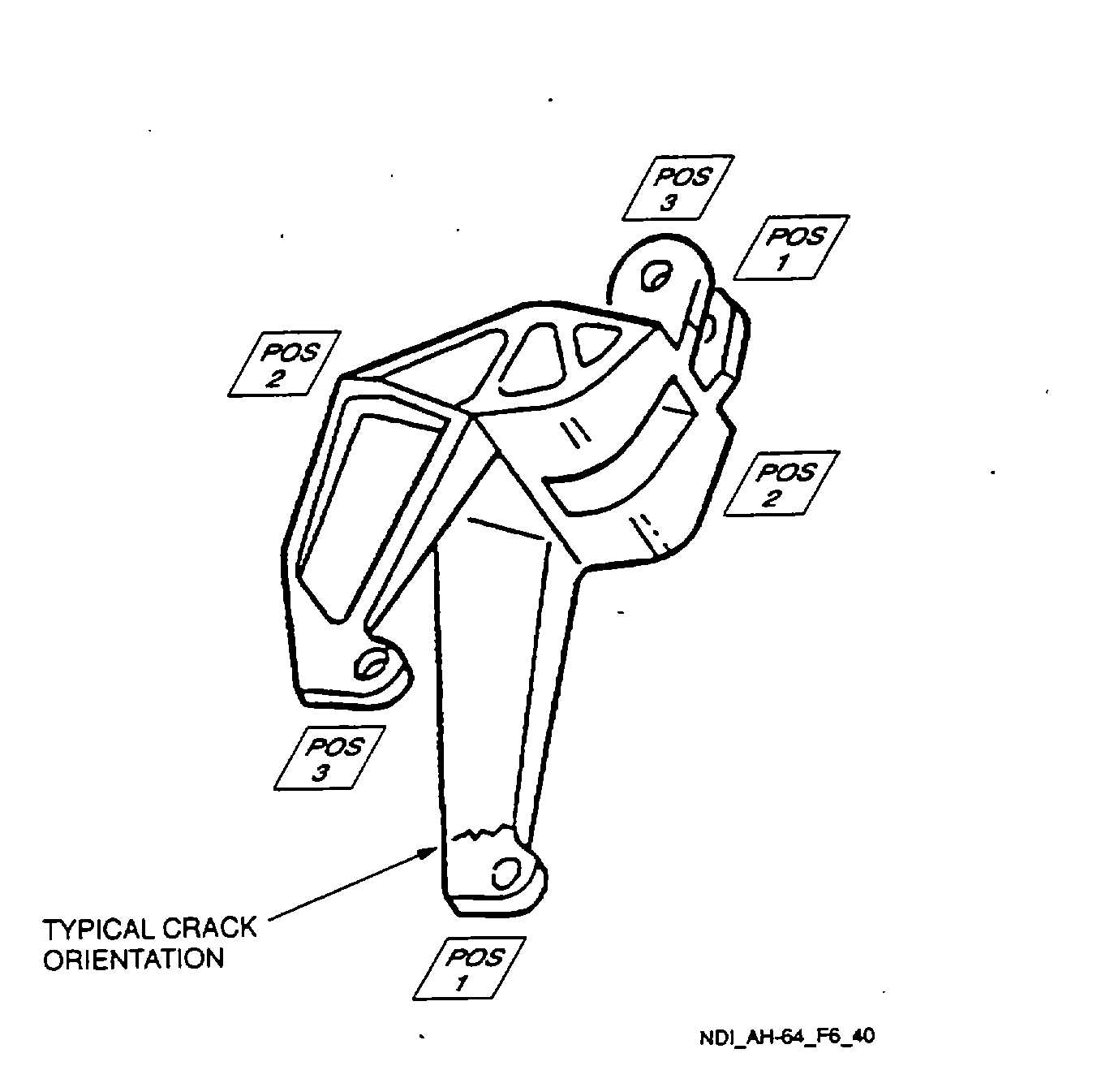
Figure 6-40. Tail Rotor Swashplate Control Bellcrank
6.40.3.8
Demagnetization. With the switch remaining in the AC position, place the probe/yoke legs in the same
position used for magnetizing. Press the test switch and withdraw the probe/yoke from the part for a distance of two feet
before releasing the switch.
6.40.4
Backup Method. None required.
6.40.5
System Securing. Clean the tail rotor swashplate control bellcrank thoroughly to remove all residual magnetic
particle media. Refer to Post Cleaning and Restoration of Part or Area After NDI, paragraph 1.4.16. The tail rotor
swashplate control bellcrank, if removed, requires installation in accordance with the applicable technical manuals listed
in Table 1-1.
6.41
TAIL ROTOR DRIVE LINKS (ET ).
6.41.1
Description (Figure 6-1. Index No. 41). There are two tail rotor drive links. The inspection is the same for
each. The tail rotor drive links are two-part links which connect the tail rotor swashplate to a controlling fork.
6.41.2
Defects. This inspection is used to verify crack indications found visually on the tail rotor drive links. No
cracks are allowed.
6.41.3
Primary Method. Eddy Current.
6-86