TM 1-6625-476-30
3-34
3-12. PNVS NSA REMOVAL FROM NIGHTSIDE TEST BENCH. (CONT)
NOTE
If white line and groove are missing, mark a vertical line on rim of PNVS
NSA with a felt tip pin in line with center of the NSA alinement pin.
(4) Install PNVS shroud assembly as follows:
NOTE
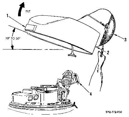
Point (1) in figure 3-24 refers to bottom surface of shroud balance weight.
Point (2) refers to shroud surface just below bottom edge of shroud
window.
(a) Grasp shroud at points (1 and 2, figure 3-24), ensuring that you do not apply pressure to
window cover assembly (3).
(b) Tilt shroud balance weight (1) up 20 to 30 degrees.
(c) Position tilted shroud directly above PNVS NSA with shroud window cover (3) directly
above elevation mirror (4).
Figure 3-24. Shroud Tilting Prior to Installation on PNVS NSA

