TM 1-6625-476-30
3-35
3-12. PNVS NSA REMOVAL FROM NIGHTSIDE TEST BENCH. (CONT)
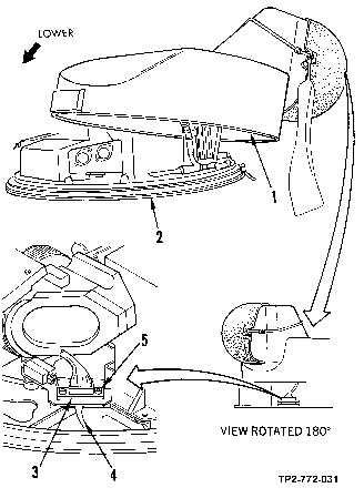
(d) Carefully lower shroud along a sloped direction toward PNVS NSA. Stop when shroud rim
area (1, figure 3-25) under window cover is no more than 6 inches above NSA mounting
base (2).
NOTE
Steps (e) and (f) require two persons. One person must support shroud
assembly while second person connects and tightens connector P1.
(e) Connect shroud connector P1 (3) to PNVS NSA connector P1 (4).
(f) Alternately tighten connector screwlock screws (5).
(g) Continue lowering shroud along a sloped direction and stopping when shroud rim (1,
figure 3-26) under window cover is approximately 1/2 inch above mounting base rim (23)
of PNVS NSA.
(h) On PNVS turret serial numbers 00001 through 00013, aline white alinement stripe (3) on
shroud with pin mark (4) on NSA rim.
Figure 3-25. Shroud Cable Connector P1 Installation on PNVS NSA