
TM 1-7010-386-12&P
CONTROLS AND INDICATORS
0004 00
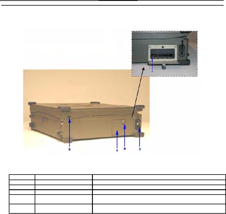
Figure 2 illustrates the controls and connectors located on the right side of the PCU with a brief description of
each of their functions.
Figure 2. PCU Right Side View Controls and Connectors
Item No.
Item Name
Description and Use
1
PCMCIA Card Bay
Bay contains slots for insertion of PC Cards.
2
PCMCIA Card Eject Buttons
Buttons are pressed to eject PC Card from adjacent PC Card slot.
3
PCMCIA Card Cable Clamp
Used to provide strain relief for PC Card external cabling.
4
PCMCIA Card Access Door
Rotated counterclockwise to unlatch the access door. Rotated clockwise to
Fastener
ensure the access door is in the closed position.
5
Display Latch Buttons
Used to secure the display assembly in the closed position for transportation.
Press to release the display.
0004 00-2