TM 55-1500-345-23
CODE
WORDING
DIRECTIONS
NO.
WARNING
INSTALL
UH-1D. Locate decal on aft side of station
65
166 bulkhead above the 204-060-499
204-060-494-1 FITTING IN TURBO
bracket, 1/2-in. black letters.
FAN INLET HOUSING AND 205-060-494-1
FITTING IN BLEED AIR
HEATER VALVE OUTLET WITH
T53-L-9A OR T53-L-11 ENGINE
INSTALLATION.
OIL TANK VENT
66
Bottom right side of fuselage, top of letters
to aircraft centerline, 1/2-in. black letters.
HEATER DRAIN
Bottom right side of fuselage, top of letters
67
to aircraft centerline, 1/2-in. black letters.
STRUCTURAL PANEL REQUIRED FOR JACKING,
Bottom sides of access panel aft of rear
68
TOWING, HOISTING, GROUND RUN AND FLIGHT.
cross tube, 1/4-in. MIL-C-46168, aircraft
black, no. 37038 letters.
FUEL CELL DRAIN
Bottom of fuselage, left and right side, top of
69
letters to aircraft centerline, 4 required,
1/2-in. black letters.
FUEL CELL CAVITY
Bottom of fuselage, left and right side, top of
70
letters to aircraft centerline, 4 required,
DRAIN & VENT
1/2-in. black letters.
BATTERY VENT
1/2-in. black letters on vents, 2 places.
71
STRUCTURAL TUBE REQUIRED
72
Locate on structural tube (P/N
205-030-249-9) right hand side of fuselage
FOR GROUND RUNG AND FLIGHT
between WL 36 and 55, and between sta-
tion 211 and 243. 1/4-in. orange-yellow let-
ters.
73
Apply "No step" to center of cowling sup-
ports (P/N 205-030-407-41/-42) on each
side facing away from walkway area. 1-1/2
inch black letters.
NO STEP
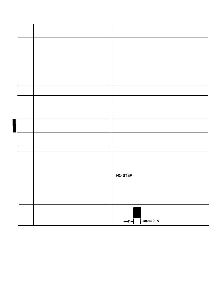
74
Stencil "No Step" on improved particle sepa-
rator, upper half, 1/2 in. MIL-C-46168, Air-
craft black No. 37038 letters, 2 places
2 IN.
75
Exhaust heat suppressor kit (P/N
205-706-082-1) LH and RH side shields, 2
in. black stripe to show turbine wheel loca-
tions as shown in detail A
(Sheet 16 of 17)
Figure 9-37. Exterior Markings, UH-10 and UH-1H
Change 8


