
TM 55-1510-215-10
(Figure 2-10 sheet 1 of 2)
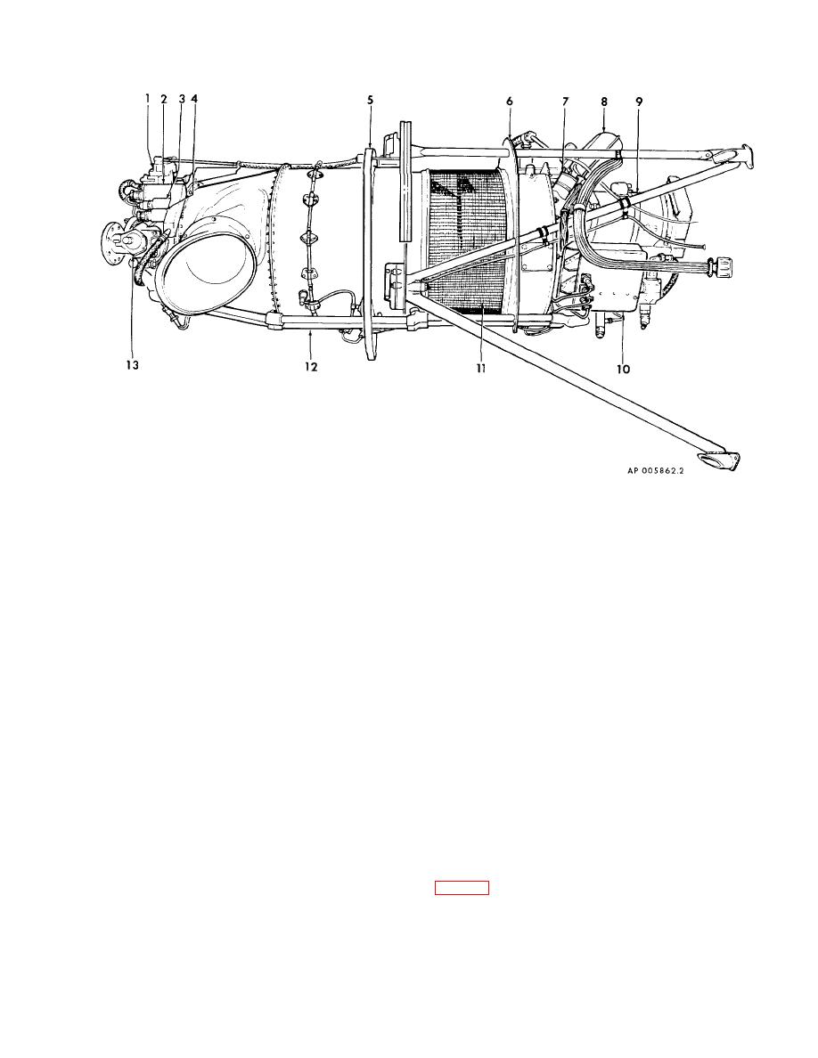
(Figure 2-10 sheet 2 of 2)
1.
Propeller governor
8.
Oil-to-fuel heat exchanger
2.
Torque pressure transmitter
9.
Starter/generator
3.
Auto ignition pressure switch
10.
Ignition regulator box
4.
Auto feather pressure switch
11.
Air intake screen
5.
Center fireseal
12.
Oil scavenge tubs
6.
Rear fireseal
13.
Propeller overspeed governor
7.
Oil filler cap and dipstick
Figure 2-10. T74-CP-700 Engine (sheet 1 of 2)
separate air scoop attached to the lower section of the
propeller thrust is used. This system is for use during
nacelle. Special components of the engine induction
landing operation only. It is comprised of plumbing
system protects the power plant from icing and foreign
which routes engine bleed air through a control valve
object damage.
into the bypass air duct mounted aft of the engine oil
cooler. When opened, bleed air-flow causes an increase
2-21. Foreign Object Damage Control.
in the velocity of the air passing through the engine air
intake. The increased air velocity prevents dust particles
The engine has an integral air inlet screen designed
present in the air from making the sharp turn up into the
to obstruct objects large enough to damage the
engine plenum chamber, forcing them to follow the air
stream out through the bypass duct. The control valve
mounted on top of the bypass duct, is normally closed
2-22. Inlet Air Separator System.
blocking the flow of bleed air. Both engine particle
separator systems are controlled by one INLET AIR
a. An inlet air system is designed to prevent the
SEPARATOR SWITCH ON THE LEFT SUBPANEL
engines from ingesting dust and foreign matter when the
aircraft lands on unimproved runways and reverse
2-15
