TM 55-2640-231-23
1-21. Temperature Measurement System. The temperature measurement system has four chromel-
alumel single junction thermocouples in the gas producer turbine outlet (TOT) and an associated integral
harness. The voltages of the four thermocouples are electrically averaged in the assembly and delivered
by the assembly lead to an engine terminal block for attachment to the airframe temperature indicating
system.
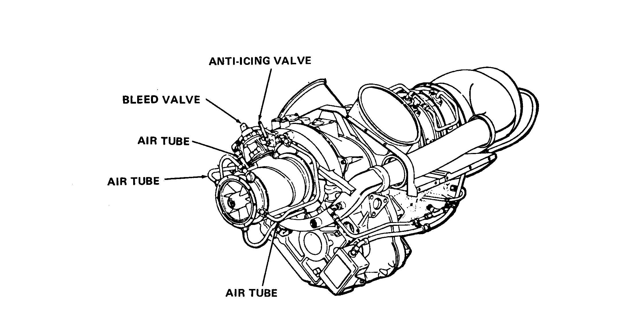
1-22. Anti-Icing System. Anti-icing (fig. 1-13) is provided for the compressor inlet guide vanes and
front support hub by the use of compressor discharge air.
The air is taken from a port at the twelve
o’clock position on the front face of the diffuser scroll. An anti-icing air shutoff valve is installed in the
port and is manually operated from the flight deck to control anti-icing air flow. Anti-icing air tubes
direct the flow of air from the valve to fittings on each side of the compressor front support. The air is
then routed through an annuris around the OD of the front support and through the inlet guide vanes
and is discharged into the inlet air stream.
Figure 1-13. Anti-Icing System
1-23. Acceleration Bleed Air System. The compressor bleed air system permits rapid engine response.
The system has a compressor discharge pressure sensing port on the scroll, tubing from the sensing port
to the bleed valve, a compressor bleed control valve (fig. 1-14) and a bleed air manifold on the
compressor case.
Elongated slots between every other vane at the compressor fifth stage bleeds compressor air into a
manifold, which is an integral part of the compressor case. The manifold forms the mounting flange for
the compressor bleed control valve when the compressor case halves are assembled.
Compressor discharge air pressure sensing, for bleed control valve operation, is obtained at a sensing
port on the compressor scroll. The bleed control valve is normally open; it is closed by compressor dis-
charge pressure.
1-20
Change 6