TM 55-2840-241-23
5-14 Change 19
(11) Adjust the aircraft linkage as outlined in the
applicable Aircraft Maintenance Manual.
(12) Test the engine as outlined in Chapter 10.
(13) Make appropriate entry relative to governor
replacement in the engine log.
5-14. Double Check Valve.
a. Removal.
CAUTION
Do not torque through the double check
valve or accumulators, internal damage
could result, use adjacent hexagonal sur-
faces for turning. When the double check
valve or accumulators are removed, use
extreme care to prevent foreign materials
from entering the pneumatic lines, valve,
or accumulators.
(1)
Hold union (60, figure 5-3) and disconnect air
hose (15) from accumulator (58).
(2)
Hold elbow (61) and remove left accumulator
(58). Discard preformed packing (59).
(3)
Remove nut (53), washer (54), spacer (55),
and bolt (57) securing clamp (56) to the firewall shield.
Remove the clamp from the check valve.
(4)
Hold right accumulator (58) and remove
double check valve (62). Remove elbow (61) and union
(60) from the double check valve. Discard preformed
packing (59).
b. Inspection. Inspect general condition of valve
and check associated tubing for cracked coupling nuts
and chafed surfaces. If crack in coupling nut is sus-
pected, refer to TM 1-1520-254-23, Technical Manual
Aviation Unit Maintenance (AVUM) and Aviation Inter-
mediate Maintenance (AVIM) Manual Nondestructive In-
spection Procedure for OH-58 Helicopter Series.
c. Installation.
(1)
Install elbow (61, figure 5-3) and union (60)
with new preformed packing (59) in double check valve
(62). Tighten the elbow and union to 55-80 in. lb.
(2)
Place a new preformed packing on right ac-
cumulator (58). Do not lubricate the preformed packing.
Screw check valve (62) onto the accumulator. Hold accu-
mulator (58) with a backup wrench and tighten the check
valve by turning on the narrow hexagonal surface adja-
cent to the accumulator. Tighten to 40-65 in. lb.
(3)
Install clamp (56) on the double check valve.
Attach clamp to firewall shield with bolt (57), spacer (55),
washer (54), and nut (53). Tighten the nut to 35-40 in. lb.
(4)
Place a new preformed packing on left accu-
mulator (58). Do not lubricate the O-ring. Screw the accu-
mulator into elbow (61). Hold elbow (61) with a backup
wrench and tighten the accumulator by turning on the
narrow hexagonal surface adjacent to the elbow. Tighten
to 55-80 in. lb.
(5)
Connect air hose (15) to the accumulator and
tighten to 80-120 in. lb.
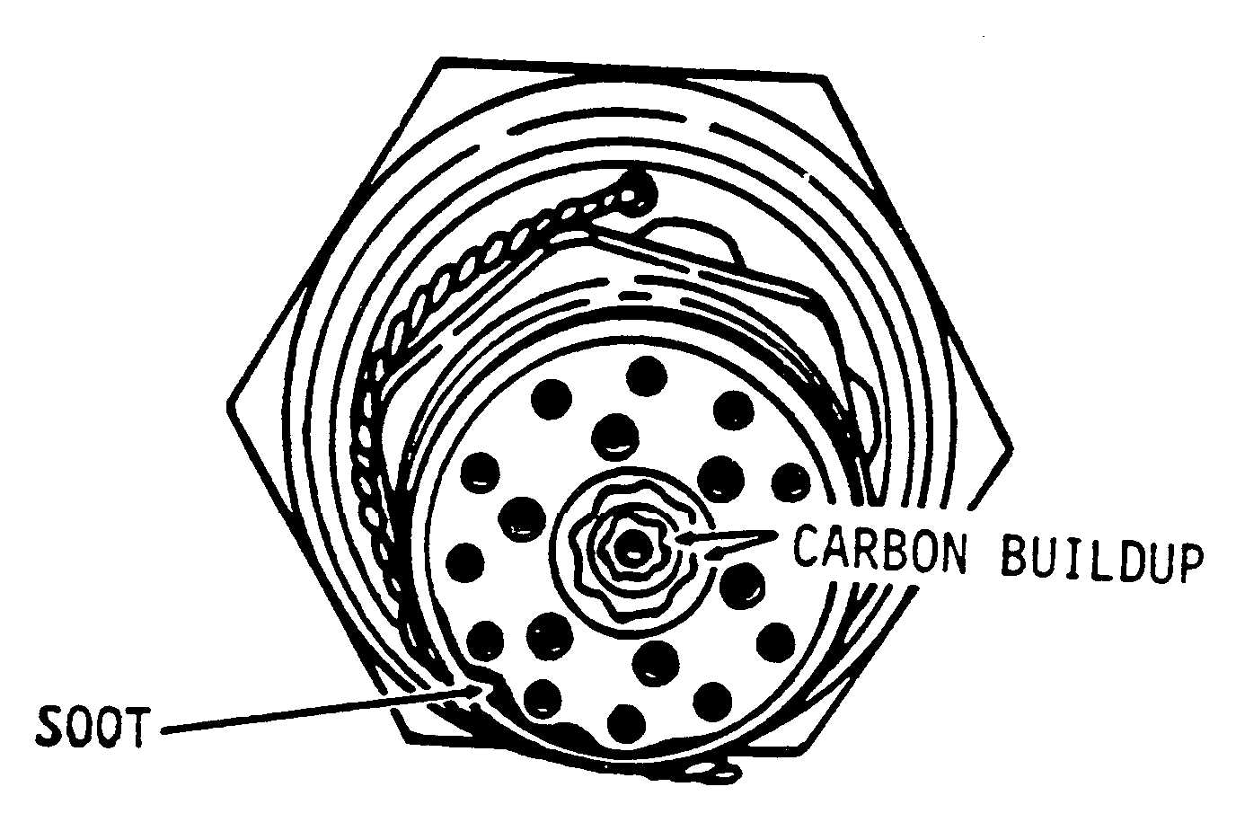
Figure 5-9. Carbon Buildup on Fuel Nozzle
(6)
Perform a fuel system pneumatic leak check.
(Refer to paragraph 5-8.)
5-15. Fuel Nozzle.
a. Removal.
(1)
Disconnect the fuel hose at the fuel nozzle (6,
figure 5-3).
CAUTION
Care must be taken when removing the
nozzle from the outer combustion case to
prevent damage to the nozzle spray tip. If
the spray tip is damaged, the nozzle must
be replaced.
(2)
Remove the lockwire and unscrew the
nozzle from the outer combustion case. Carefully extract
the nozzle from the combustion case.
NOTE
To preclude the possibility of the combustion
chamber becoming misaligned, do not re-
move the fuel nozzle and the spark igniter at
the same time.
b. Cleaning.
(1)
Check for carbon deposits on the spray tip.
Figure 5-9 shows the condition of a typical fuel nozzle
removed from an operational engine. A nozzle in this
condition should be cleaned, if possible, before being
reinstalled.