TM 55-2840-241-23
(2) If the filter was not heavily contaminated,
accomplish steps j through l.
h. Drain the oil from the engine oil system. (Refer
to paragraph 5-20.)
i. Fill the oil tank with the desired oil and release
the engine for service.
j. After five hours operation, inspect and clean or
replace the oil filter.
k. After 15 hours operation since oil change, in-
spect and clean or replace the oil filter.
l. Revert to normal schedule of inspection of oil
filter.
5-22. Mixing of Engine Oils.
Do not mix MIL-L-7808 and MIL-L-23699 oil ex-
cept in an emergency. If mixing is necessary, flush the
system within six hours of engine operation, (Refer to
paragraph 5-21.)
5-23. 0i1 Tubing and Fittings.
The tubes used in the oil system are rigid stainless
steel assemblies incorporating permanent fittings.
a. Inspect oil tubes for kinks, uniformity of
diameter, breaks, and freedom from interference with
adjoining structure or other components. Replace de-
fective oil tubes.
b. Inspect fittings and hardware for cracks, cross-
ed threads, obstructions in openings, burrs, or other
damage. Replace all damaged fittings. Replace all
seals, packings, and lockwire when they are removed
from a unit. If cracks in fitting or hardware are sus-
c. Tighten No. 4 size coupling nuts to 80-120 in. lb
and No. 5 size coupling nuts to 150-200 in. lb.
5-24. Magnetic Chip Detectors.
Each chip detector consists of a magnetic plug
with a single pin electrical receptacle. The threaded
plug portion of the chip detector includes a terminal
shaft and. pole piece separated from a magnet in the
plug body by insulators. When ferrous metal particles
are sufficient in size of accumulation to bridge the gap
between the pole piece and the magnet, an electrical
(ground) circuit between the chip detector and the
ENG CHIP DET indicator light is completed.
a. Removal. Remove lockwire and unscrew
magnetic chip detector. Some oil spilling is likely.
Remove preformed packing from plug and discard
preformed packing.
NOTE
When removing chip detector, care should be
taken not to contaminate detector.
b. Inspection.
(1) Visually check each plug for metal ac-
cumulation.
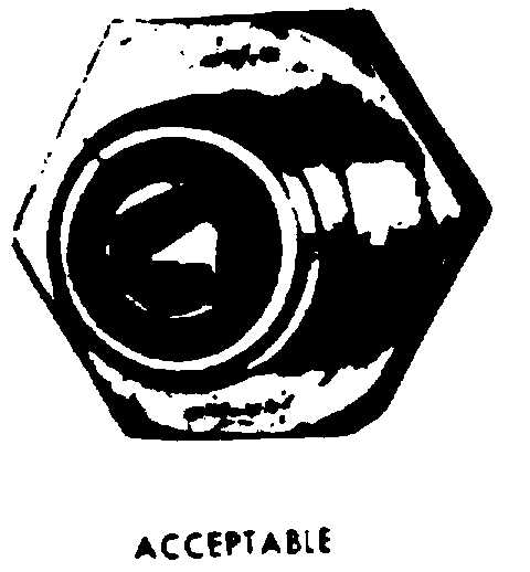
(2) Flakes of magnetic material of 1/16 in. or
more diameter are indications of an incipient failure
and are cause for engine removal. (See figure 5-10.)
(3) Fuzz or hair-like magnetic particles can
normally be found on the magnetic plug and are not
cause for engine replacement. (See figure 5-10.)
c. Cleaning. Wipe chip detectors with a clean,
lint-free cloth.
d . I n s t a l l a t i o n .
I n s t a l l a n e w p r e f o r m e
packing lubricated with oil (item 7, table 2-2) on
magnetic plug. Install magnetic plug; tighten to 60-
80 in. lb and lockwire.
e. Testing—Chip Detector and Circuitry.
(1) Place BATT-OFF switch to OFF and
apply external power.
(2) Remove chip detector.
Figure 5-10. Particle Accumulation on
Magnetic Chip Detector
Change 23 5-17
254539
pected, refer to TM 1-1520-254-23, Technical Mnual
Aviation Unit Maintenance (AVUM) and Aviation
Intermediate Maintenance (AVIM) Manual Nondes-
sructive Inspection Procedure for OH-58 Helicopter Series.


