TM 55-2840-241-23
Change 19 5-20.1/(5-20.2 blank)
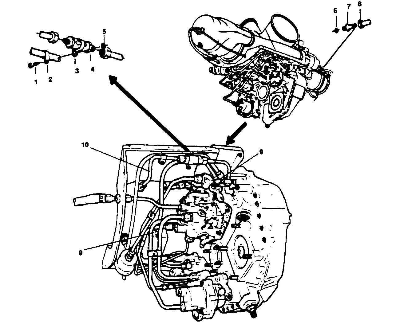
1.
Bolt
6.
Preformed packing
2.
Clamp
7.
Oil pressure reducer
3.
Clamp
8.
Oil tube
4.
Check Valve
9.
Tube nuts
5.
Nut
10.
Tube
Figure 5-12. External Oil Check Valve
5-30.1 Oil Pressure Reducer.
a. Removal.
(1)
Disconnect the oil tube (8, figure 5-12) from
the oil pressure reducer (7).
(2)
Remove the oil pressure reducer from the
compressor front support. Discard preformed packing
(6) and oil pressure reducer (7).
b. Installation.
(1)
Lubricate new preformed packing (6) with oil
(item 7, table 2-2) and place on new oil pressure reducer
(7).
(2)
Install the oil pressure reducer on the com-
pressor front support and tighten to 50-75 in. lb.
(3)
Connect the oil tube (8) to the oil pressure
reducer and tighten coupling nut to 65-100 in. lb.
5-30.2 Scavenge Oil Flow Check.
a.
Measure the quantity of oil flow from the power
turbine support scavenge oil external sump. To ensure
consistency make the measurement during the following
conditions:
(1)
Engine oil temperature not cooler than 10 C
(50 F) or hotter than normal operating temperatures.
(2)
Use external power source to ensure N1
rotation of 16% (TM 55-1520-228-23).
(3)
Remove the external sump to gear box scav-
enge oil tube by loosening tube nuts (9) and tube (10) at
the external sump and fitting. Connect clear tube (item
38, table 2-2) to the oil sump scavenge fitting to direct oil
flow.