TM 55-2840-241-23
Table 10-3 lists the power settings and se-
quence of events for performing an engine
functional test run. Perform the applicable por-
tions of the test as outlined in table 10-2. The
engine must operate within the limits specified
in table 10-1 .
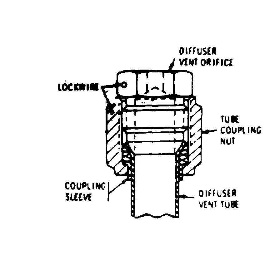
Figure 10-2. Diffuser Vent Orifice Installation
10-8. Functional Test Schedule.
10-9. Diffuser Vent Orifice Selection.
If the compressor shows evidence of oil
leaks e or smoking at the diffuser vent tube,
select a new orifice as follows:
a. Clean the area around the orifice.
b. Perform settings 7 through 10 of the test
run schedule in tab e 10-3.
c. After the test run, inspect the area around
the orifice. If there is any evidence of smok-
ing or spewing from the vent, reduce the
orifice size by installing the next lower dash
number orifice. (See figure 10-2.) Secure the
orifice with lockwire (item 32, table 2-2).
When the engine is to be tested onn the test
stand, drain bottles shall be provided to collect
drainage from the burner drain valve, fuel
pump seal drain, firewall shield drain and ex-
haust collector drain. Combine drainage shall
not exceed 2 cc/minute, except fuel pump seal
drainage shall not exceed 0.5 cc/minute, of
t h i s t o t a l .
d. Repeat the run, inspection, and orifice re-
placement until no evidence of spewing or
smoking is present.
10-9.1. Diffuser Vent Tube Requirement
a. Remove lockwire, loosen coupling nut
and separate the diffuser vent orifice from the
diffuser vent tube. (See figure 10-2.)
b. Remove the bolt, washer and clamp.
Separate the diffuser vent tube from the rear
diffuser.
c. Install the diffuser vent orifice in the dif-
fuser vent tube. Secure vent tube with bolt,
washer and clam . Secure coupling nut to
vent orifice with lockwire (item 32, table 2-2).
10-10. Fuel Requirements.
The fuel used for testing shall conform to
item 33, table 2-2. The fuel suppIy system
shall be capable of supplying 350 pounds per
hour flow over the range of 5 to 45 psig inlet
pressure. A sufficient number of 5 micron
#200 mesh screen) filter elements shall be
provided to adequately falter the fuel and allow
the required flow rate.
10-11. Lubricating Oil Requirements.
The engine lubricating oil used for testing
shall conform to items 7 or 8, table 2-2.The
oil supply system shall be capable of maintain-
ing oil inlet pressure within 0-1.8 psig and
oil inlet temperature within the range of 180 to
225°F. A suffcient number of 25 micron fil-
ters shall be provided to adequately filter the
scavenge oil.
10-12. Electrical Supply Requirements.
a. The ignition exciter requires a d-c power
supply of 28 volts (4 amps minimum).
b. The starter requires a source of external
power capable of 350 to 400 amperes, and 28
volts is recommended for starting the engine
however, limits of 300 to 750 amperes and 28
volts are allowable for starting the engine.
10-13. Drainage Requirements.
10-14. Preservation Requirements.
Engines which are not scheduled for im-
mediate installation into the airframe shall be
preserved as outlined in Chapter 3.
Change 16
10-7


