TM 55--2840--254--23
Change 6 4--425
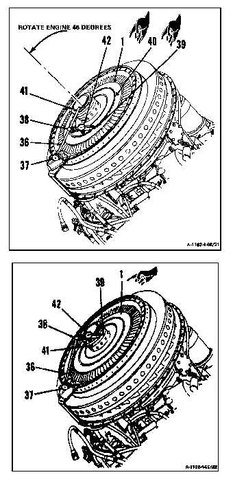
4--66 INSTALL FIRST TURBINE DISC ASSEMBLY (AVIM) (Continued)
4--66
c. Rotate engine to approximately 45 degrees.
NOTE
In following step d., be sure pointer is
on disc rim and not on retaining plate.
d. Adjust arm (36) at base (37) and clamp (38)
to position pointer (39) on outer surface (40)
adjacent to blade roots.
NOTE
When checking runout, apply forward
pressure to hub (41) to compensate for
bearing internal clearance.
e. Zero indicator (42) and rotate first turbine
disc assembly (1). Record dimension. Maxi-
mum allowable runout shall be 0.004 inch.
f. Adjust arm (36) at base (37) and clamp (38)
position pointer (39) on hub (41).
g. Zero indicator (42) and rotate first turbine
disc assembly (1). Record dimension. Maxi-
mum allowable runout shall be 0.002 inch.
NOTE
If dimensions recorded in steps 13.e.
and 13.g. are not within limits, do follow-
ing steps 14. thru 21. If dimensions re-
corded in steps 13.e. and 13.g. are with-
in limits, omit steps 14 thru 21.
INSPECT
GO TO NEXT PAGE