TM 55-4920-328-13
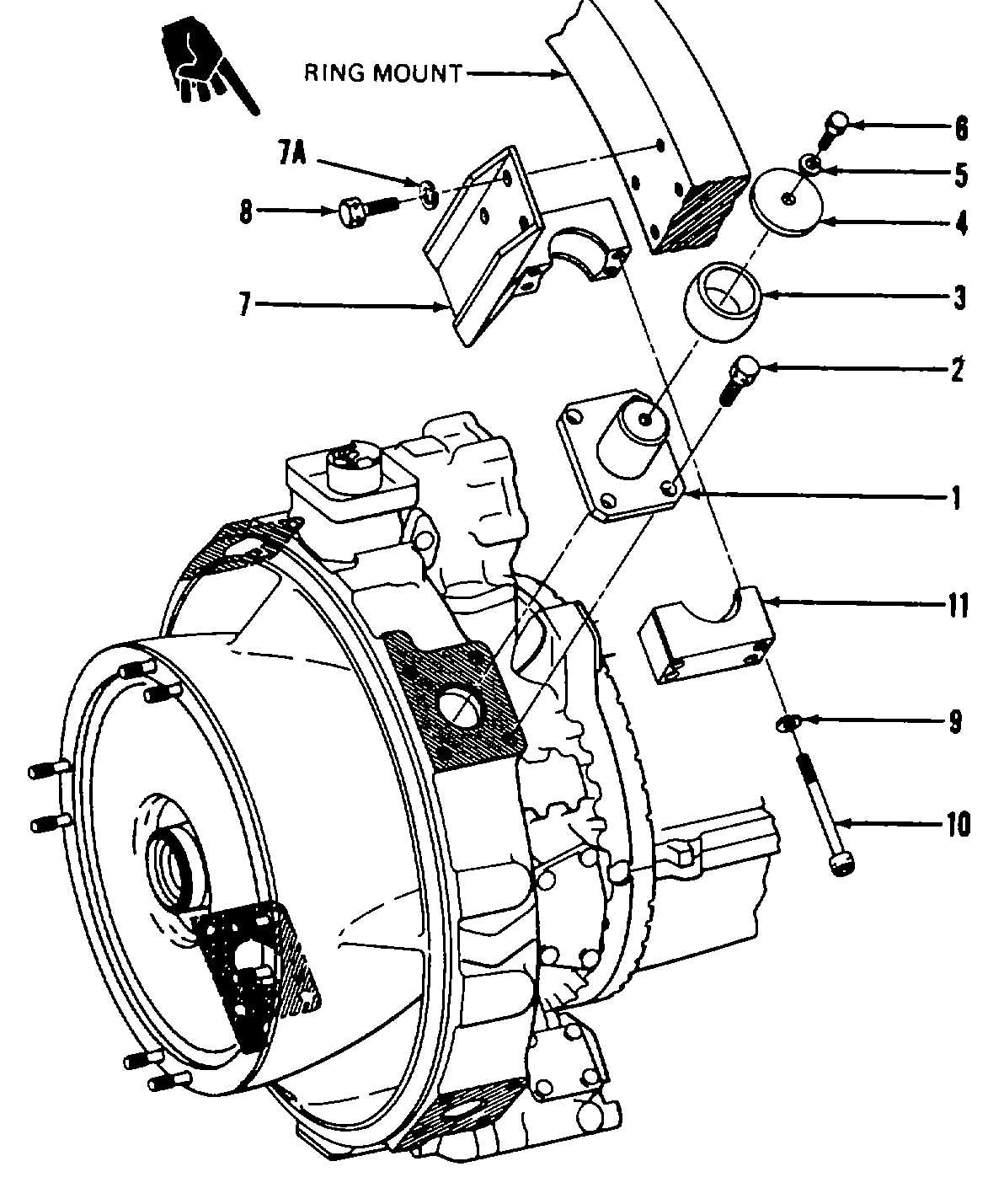
Figure 2-23. T55 Turboshaft Engine Mount Installation.
(5) Install hydraulic starter (7) and gasket (6) on
engine starter mounting pad.
NOTE
U.S. Army (USATSARCOM) author-
ized ECP No. MEG-01, dated March
26, 1981, identifies the replacing of
the gasoline engine driven hydraulic
starting unit and the battery starting
system with a Christie Rectifier
Power
Supply
starting
system.
(Army supported electrically drive
units are currently available.)
(5.1) On T55-L-712 model engines, if electric
starter is to be used in place of hydraulic starter, install
electric starter (3, figure 2-24.1) on engine starter
mounting pad.
(6) Apply molybdenum disulphide conforming to
Specification MIL-M-7866 to NI and NII tachometer
generator drive gears.
(7) Install NI tachometer generator (6), figure 2-25)
and gasket (7) on oil pump pad and secure with washers
(6B) and nuts (6A). Tighten nuts to 78 2 inch-pounds
torque.
(8) Install NIIl tachometer generator (5), gasket (4),
drive assembly (3), and packing (2) on accessory drive
gearbox and secure with washers (5B) and nuts (5A).
Tighten nuts to 78 2 inch-pounds torque.
(9) Install vibration adapter assembly (1, figure 2-
26) and vibration pickup (2) on engine aft vibration
mounting pad.
(9.1) Install bracket (76) and vibration pickup (7) on
diffuser front flange..
(10) On T55-L-7/7C model engines, remove dust
cover and install exhaust cone (17) with V-band clamp
(19). Tighten clamp to 390 10 inch-pounds torque.
Install dust cover on exhaust cone.
Change 4
2-104
1.
Engine Mount- TE6422
2.
Bolt - MS9505-11
3.
Ball - TE26838
4.
Washer - LTCT21865-01
5.
Washer - MS35338-44
6.
Bolt - MS9501-10
7.
Bracket - TE6418-02
7A.
Washer - MS35338-48
8.
Bolt - MS9505-11
9.
Washer - AN960-816
10.
Screw - LYC491-13H48
11.
Bracket Clamp - TE6418-03


