TM 1-1500-204-23-1
11-21. Restraint Equipment. Restraint equipment, as
used in this section, includes safety lap belts, shoulder
harnesses, and other fabric devices used in Army
aircraft for personnel restraint purposes. Restraint
equipment is to be installed as directed in the applicable
maintenance manual. On all pilot/copilot and crewman
seat belts, the safety belt release handle should point to
the left.
NOTE
Seat belts will not be replaced for
cosmetic reasons.
a.
Inspection. All personnel restraint equipment is
to be visually inspected at time of installation and at
specified intervals thereafter. Inspections are explained
in the following paragraphs.
·
New Restraint Equipment. Perform
daily inspection for new seat belt
latches (MS3488(AS)) also Inspect for
fingertip access.
·
New Assemblies of Restraint
Equipment This equipment requires
no inspection during depot storage.
·
Seat
belt
latch
(MS3488(AS)).
Inspect
for
fingertip
clearance.
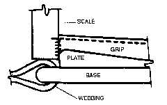
Inspect each seat belt latch by using a
steel scale to measure the clearance
distance between the inside face of
the top of the grip and the top of the
webbing, as shown In figure 11-6.
WARNING
Except for leg garters used with the
MK-5D ejection seat, all restraint
assemblies made of cotton webbing
shall be removed from service. Use
extreme caution when inspecting
restraint equipment on ejection seat
equipped
aircraft.
Ensure
appropriate safety pins are installed.
Injury to personnel may otherwise
result.
Figure 11-6. Measuring Fingertip Clearance
(1)
Installation inspection. Visually inspect all
restraint equipment prior to installation. Seat belt
latches shall be inspected for fingertip clearance in
accordance with the following procedures.
(a) Inspect each seat belt latch by using a
steel scale to measure the clearance distance between
the inside face of the top of the grip and the top of the
wedding, as shown in figure 11-6
(b) If the distance measured above is less
than the thickness of gloved fingers (minimum 0.8 inch)
alter latch using the following procedures:
1
Open latch so that sides may be
placed in vise equipped with aluminum or brass
protective plates on jaws.
2
Squeeze sides of latch handle
together using constant, even vise pressure until jaws
are approximately 1 3/4 inches apart. Latch will deform
upward and inward, as shown in figure 11-12.
3
Repeat as necessary to obtain
7/8-inch clearance dimension due to spring back of
metal.
4
Perform
visual
inspection
for
cracks.
5
Check operation of latch and
detent for complete lock and release.
11-20