TM 1-1500-204-23-2
(h) Push latch up to lock upper die block assembly into position over lower die block assembly.
CAUTION
Insufficient or too much tube insertion in the Permaswage fitting Is cause for rejection of the joint.
(i) Position face of swaging tool against location mark on tube. The outer edge of latch must fall within location
mark
WARNING
Keep hand or head away from the tool while pressure is being applied. Failure to comply may result in
serious bodily injury
(j) Set selector valve to appropriate hydraulic output.
CAUTION
Under-pressurization will result in improperly swaged joint. Over-pressurization will put undue stresses on
swaging tool, fitting, and tube.
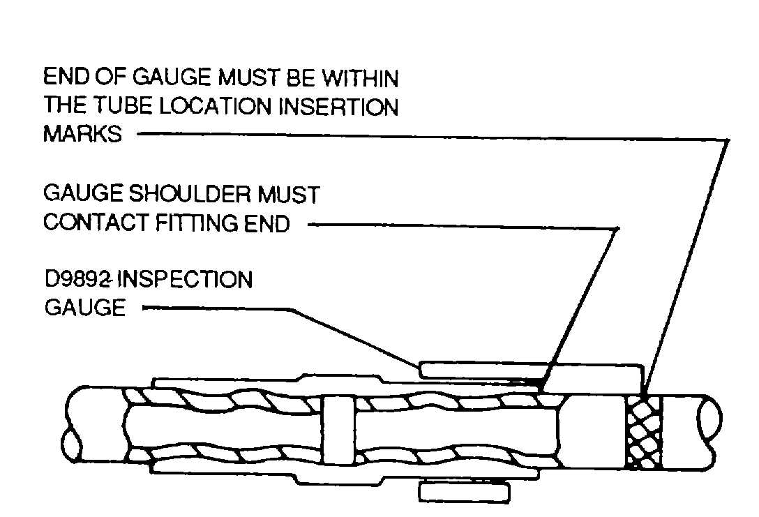
Figure 4-85. Checked Swaged Joint with D9892 Inspection Gauge
(k) Actuate swaging tool with 5,500 (+250) psi hydraulic pressure in line from hydraulic power supply. This may
be accomplished manually by pumping hand pump on hydraulic power supply until gauge indicates 5,500 psi, or
automatically by using shop-air connection and pressing local or remote air switch until gauge indicates 5,500 psi.
(I) Set selector valve to EXHAUST to relieve pressure completely
(m) Slide latch to OPEN position
(n) Remove upper die block assembly by sliding out from end of swaging( tool or up through slots in tool head
on D10001.
NOTE
If upper die block assembly is difficult to remove, check to see that pressure has been completely relieved.
(o) Remove swaging tool from swaged joint.
g. Inspection of Swaged Joint. Inspection of swaged joints is accomplished visually and with the aid of the D9892
Inspection Gauge of correct dash (-) size for the swaged fitting Proper use of the correct inspection gauge ensures.
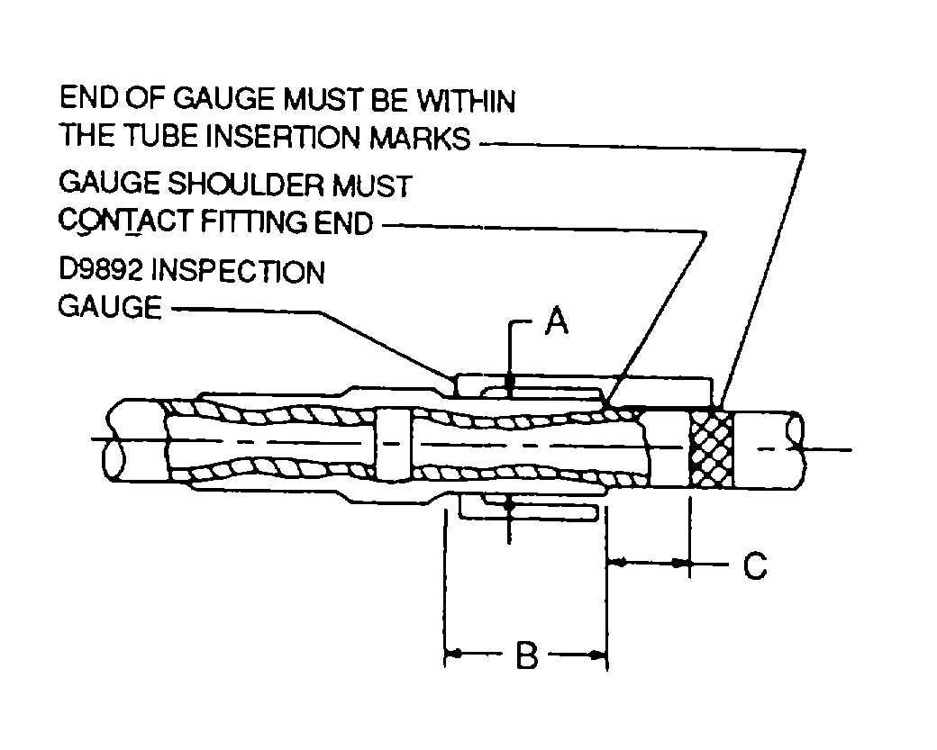
Figure 4-86. After Swage Dimensions (Use with Table 4-39)
4-96