TM 1-1500-204-23-2
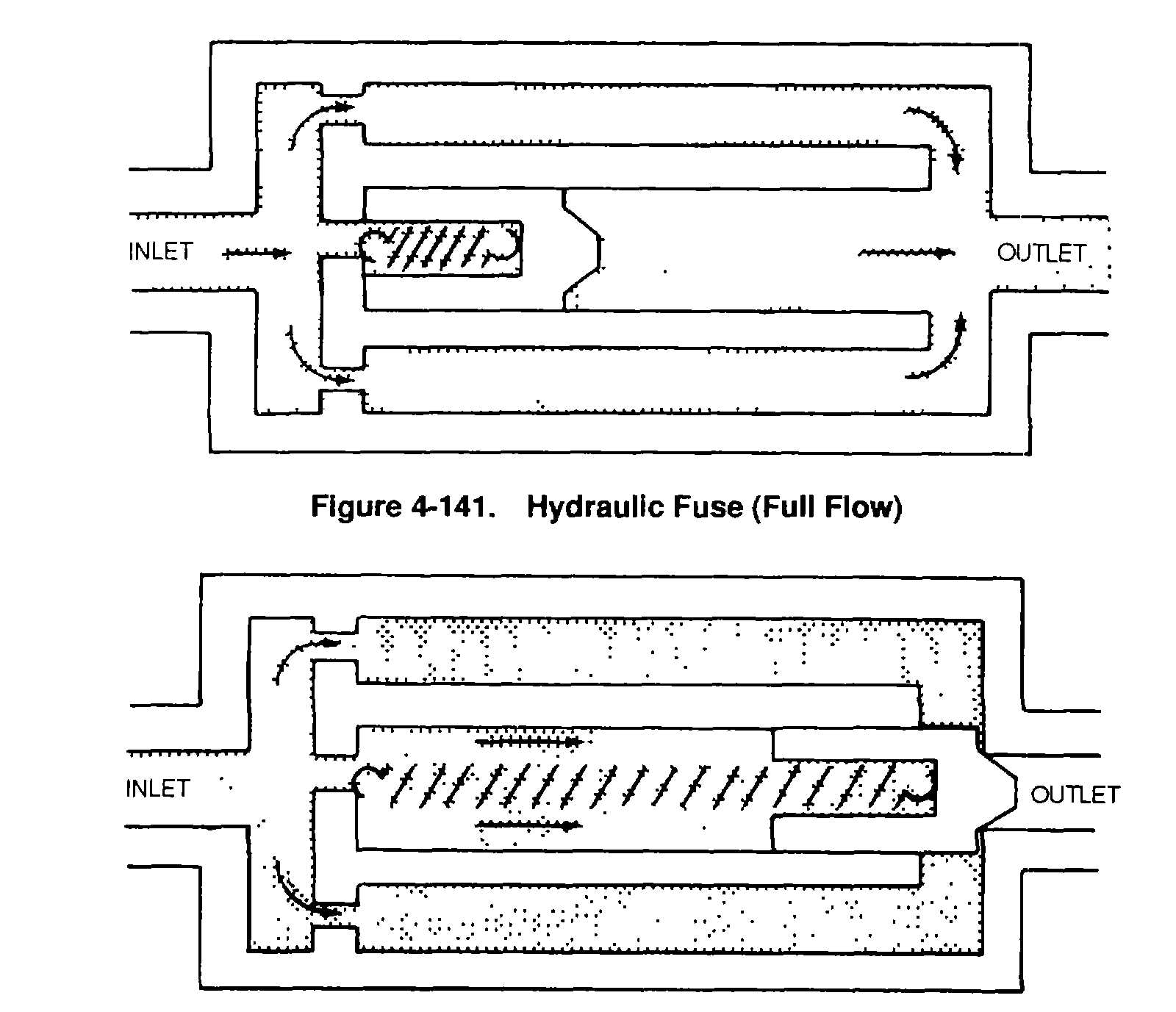
Figure 4-142. Hydraulic Fuse (Blocked Flow)
l.
Maintenance of Hydraulic Flow Control Units. Extreme cleanliness is essential. Small particles of
foreign matter lodged in assemblies will cause leakage or improper operation of the valve. Wash all parts, except
solenoids, with drycleaning solvent, Federal Specification P-D-680, and dry with compressed air.
4-17.
Types of Pneudraulic Systems. The arrangement of components within the hydraulic systems varies
among the different types of aircraft. However, all aircraft hydraulic systems incorporate the components described in
paragraph 4-16. The hydraulic system may be an open-center or a closed-center type and may be interconnected with a
pneumatic system that serves as an emergency pressure source in case the main system falls.
a.
Open-Center Hydraulic System. An open-center hydraulic system has hydraulic fluid flow but no
pressure until some actuating unit is operated. A typical basic open-center system such as the one shown in figure 4-143
consists primarily of a reservoir, a constant delivery type pump, a relief valve, one or more selector valves, and one or
more actuating units This system does not require a pressure regulator The system relief valve limits system pressure
when the selector valve is in an on position and an actuating unit is operating.
(1)
Operation of system with selector valves in off position. Fluid flows from the reservoir Into the
pump and from the pump Into the main pressure line. Because all selector valves are in the off position, the fluid passes
back to the reservoir through the open-center passage of these valves. Since no restrictions exist in the system, there is
no pressure in the system other than that caused by friction.
(2)
Operation of system with one selector valve in on position. With one selector valve in the
operating position, as shown in figure 4-144, fluid flows under pressure to the actuating unit. As the actuating unit
moves, it forces residual fluid from the piston through the open selector valve and back to the reservoir. At the end of
the stroke of the actuating unit, fluid flow becomes blocked and pressure increases within the system. Eventually, the
pressure builds up to the setting of the relief valve, at which point it is bypassed to the return line arid back to the
reservoir. This condition exists until be selector valve is returned to the neutral (off) position.
Figure 4-141. Hydraulic Fuse (Full Flow)
4-140