TM 1-1500-204-23-2
Figure 4-144. Open Center Hydraulic System (Valve Open)
b.
Closed-Center Hydraulic System. A closed hydraulic system is sometimes called a direct system
because the hydraulic fluid is under pressure throughout the system when the pump is operating. A basic closed-center
hydraulic system consists primarily of a reservoir, a pump, a relief valve, one or more selector valves, and one or more
actuating units In figures 4-145 through 4-147, each of the three selector valves controls a different actuating unit and
each valve is in a different position. Hydraulic fluid is drawn from the reservoir to the pump, which forces the fluid on to
the selector valves A, B, and C with results as described in the following paragraphs.
(1)
Selector valve A. In figure 4-145, the rotor of selector valve A is positioned so that the valve
ports are closed. The hydraulic fluid is trapped in the lines leading from the selector valve to each side of the piston in
the actuating unit. Thus, the fluid cannot move in any direction. This holds the piston in a locked position, and any
attached mechanism will be held in a fixed position.
(2)
Selector valve B. In figure 4-146, the rotor of selector valve B is positioned so as to direct the
fluid flow from the selector valve to the face of the piston in the actuating unit. This pressure forces the piston to move
outward, causing any mechanism attached to the piston rod to function. Fluid moving out of the actuating unit as the
piston moves outward flows into the return line to the reservoir.
(3)
Selector valve C. In figure 4-147, the rotor of selector valve C is positioned to direct the fluid
flow to the rod side of the piston, forcing the piston to move
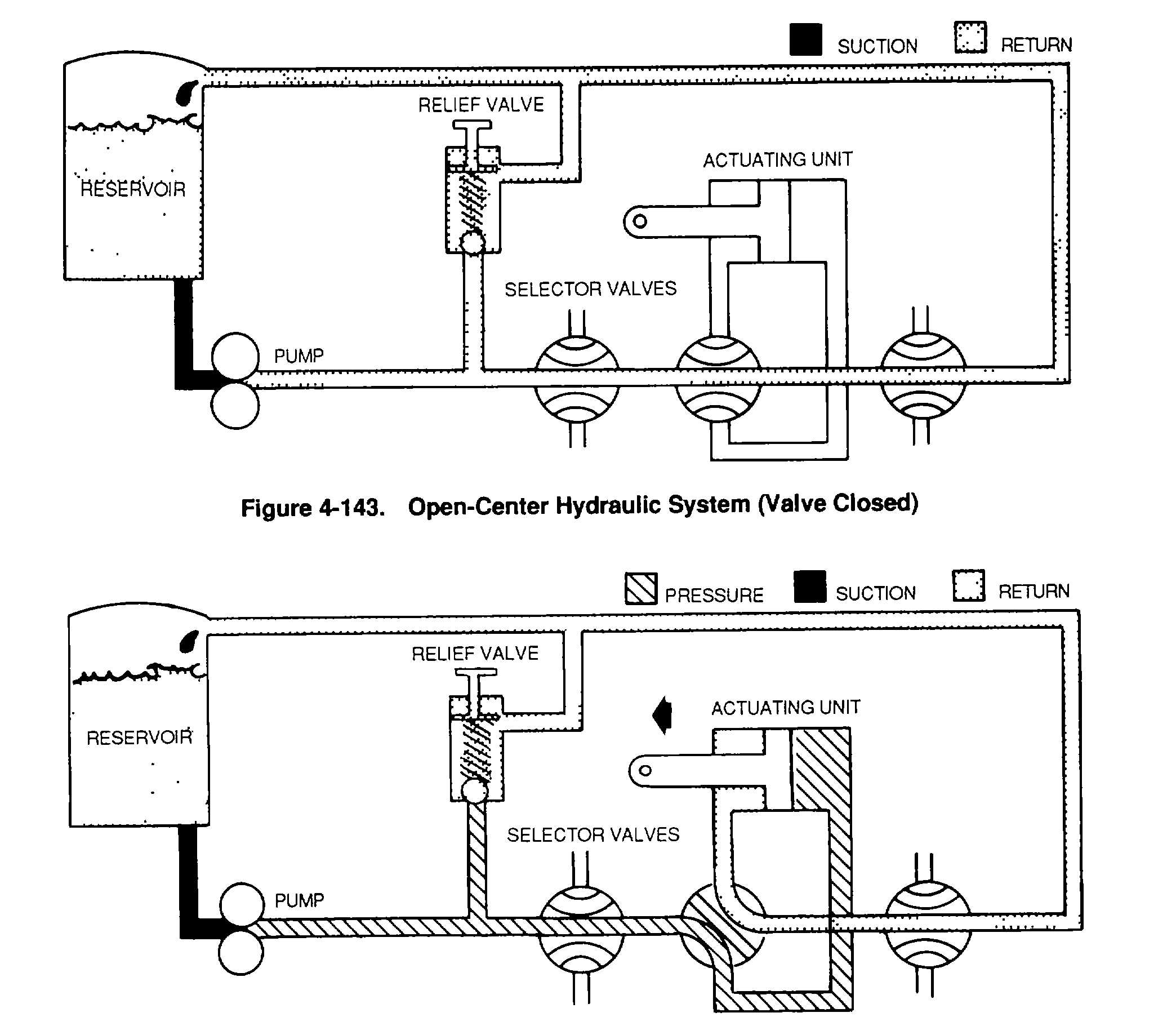
Figure 4-143. Open-Center Hydraulic System (Valve Closed)
4-141