TM 1-1500-204-23-2
(c)
Distance B. Distance B is the distance from the last bend to the end of the tube. This
measurement may be made with original measurements, but should be rechecked after final bending operation.
f
Flaring Tubing. As system pressures increase, tubing joints must be designed so as not to be adversely
affected by increasing pressures. Single flared tubing is used for tubing joints on all sizes of steel tubing, 6061 aluminum
alloy tubing, MIL-T-7081, and all sizes of 5052 aluminum alloy tubing, Federal Specification WW-T-700/4, above 1/2-
inch OD. Double flared tubing is used for tubing joints on all sizes of 5052 aluminum alloy having an OD of 1/2 inch or
less. Double flaring reduces cutting of flare by overtightening and failure of tube assembly under operating pressure.
See figures 4-7 and 4-8 for tube dimensions.
(1)
Preparing flaring tool for flaring. Before using flaring tool, clamping surfaces should be free from oil,
grease, or aluminum particles. Clamping surfaces may be cleaned with naphtha, Federal Specification TT-N-95, or
anhydrous ethyl alcohol, Federal Specification O-E-760, Class A, and a stiff fiber brush. Do not use a wire brush or steel
wool. If tubing slips in the tool during the flaring operation and the cleaning procedure does not work, clamping blocks
should be dipped in a 20 percent solution, by weight, of sodium hydroxide, Military Standard MS36037, or potassium
hydroxide, Military Standard MS36035, in water. This will remove the aluminum alloy particles. The inner surface of
clamping blocks should never be sandpapered, ground, or refinished, as this will render the tool unsatisfactory for use.
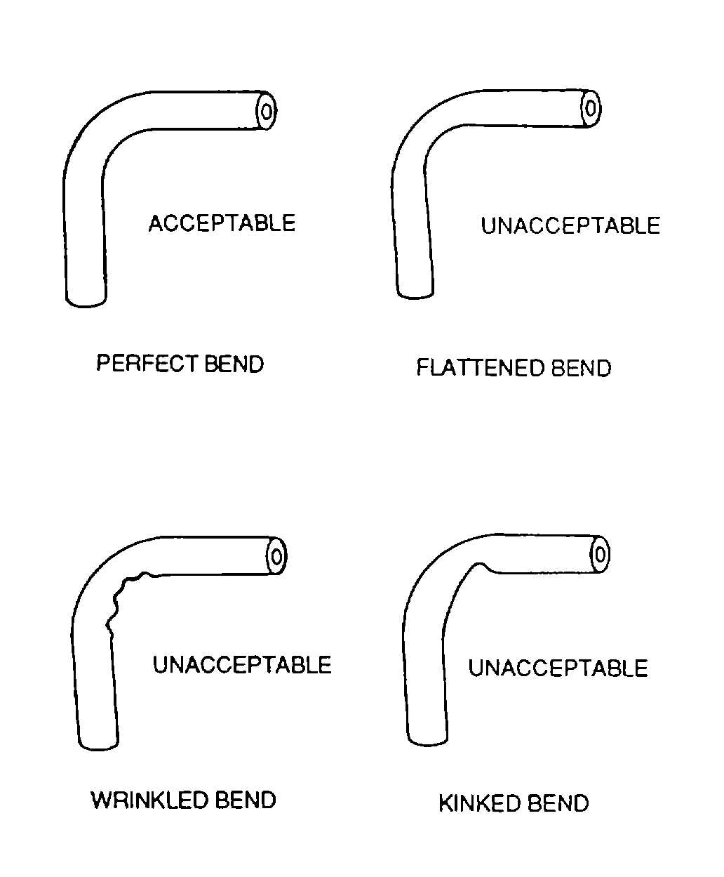
Figure 4-5. Acceptable and Unacceptable Tubing Bends
(2)
Preparing tubing end for flaring. The tubing end is prepared using the following procedures (see figure
4-9).
(a)
File end of tubing square with fine flat file.
(b)
Remove burrs from inside and outside of tubing with burring tool.
(c)
Remove all filings, chips, and grit from inside of tube.
(d)
Clean tubing.
(e)
Inspect tubing end to see if it is round, cut square, clean, and free from draw marks and
scratches. Draw marks and scratches are likely to spread and split tubing when it is flared.
(3)
Flaring tool. The flaring tool shown In figure 4-10 is suitable for producing tubing flares having a 74-
degree included angle. It will produce a double lap flare, conforming to Military Standard MS33583, on 3/16-inch through
3/4-inch mild aluminum tubing, and a single lap flare, conforming to Military Standard MS33584, on all grades of aircraft
tubing including 1/8-inch through 3/4-inch, 1/4-hard, corrosion-resistant steel. Correct use of the flare tool will give a
perfect flare. Incorrect double flares, as shown in figure 4-11, should be cut off and another flare made. A short inner
flare should not be used because of short bearing surface for the fitting nipple. The short inner flare is caused by
inserting tubing too low in clamp blocks or by tubing slipping during flaring operation. Improper tightening, jamming of
tightening screw, or dirt on inner surface of clamp blocks will cause tubing to slip. A long inner flare should not be used
because it will restrict fluid flow. The long inner flare is caused by improper gauging.
4-6


