TM 1-1500-204-23-3
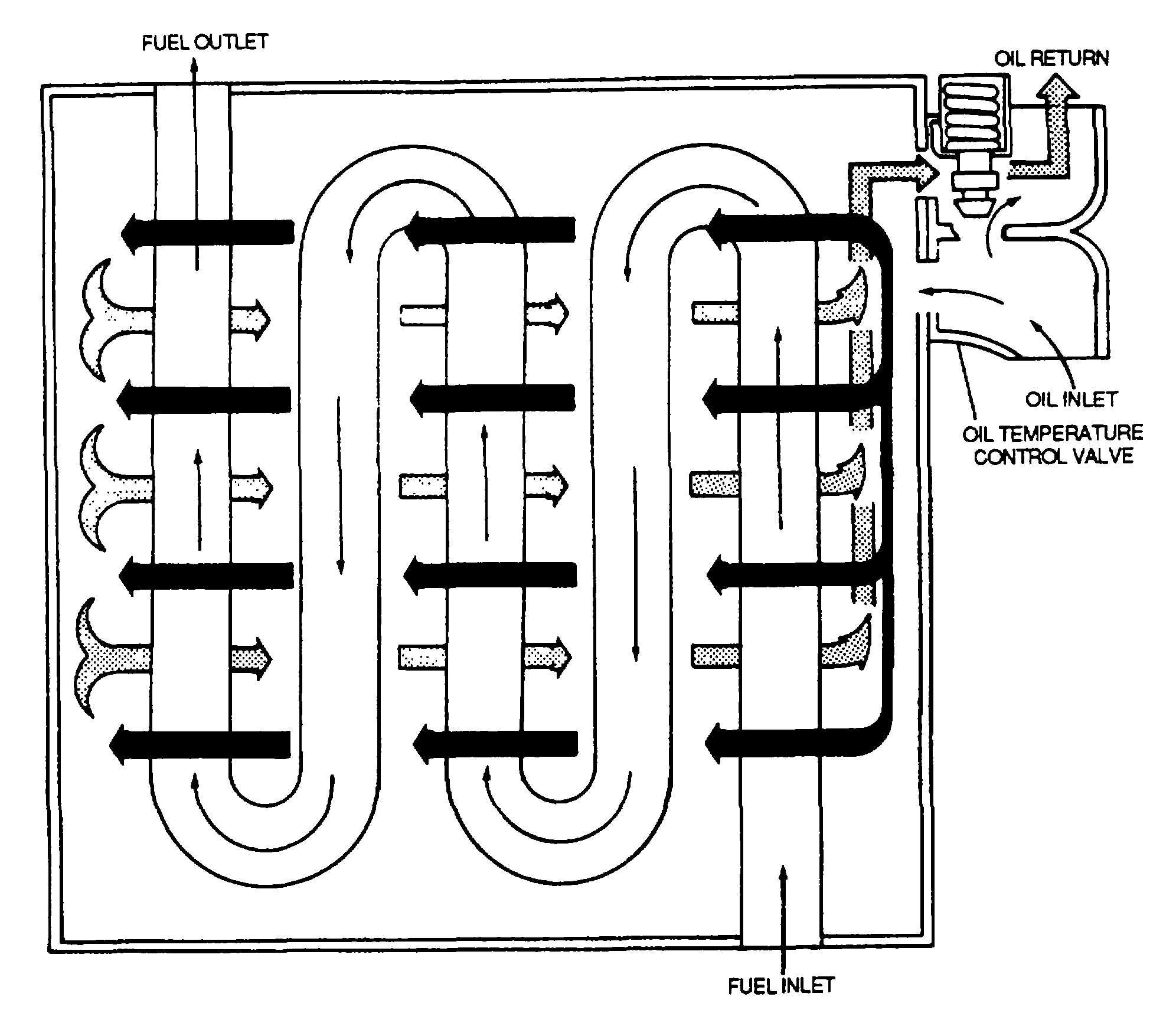
Figure 3-11. Turbine Engine Fuel/Oil Heat Exchanger Cooler
(4)
Surge valves. Surge valves are used to prevent high oil pressure from bursting the oil cooler or blowing
hose connections. Figure 3-14 shows a surge valve incorporated in the oil cooler flow control valve. The high-pressure
operation condition is shown in figure 3-14, where the high oil pressure at the control valve inlet has forced the surge
valve upward. Note how this movement has opened the surge valve and, at the same time, seated the poppet valve.
The closed poppet valve prevents oil from entering the cooler proper; therefore, the scavenge oil passes directly to the
tank outlet without passing through either the cooler bypass jacket or the core. When the pressure drops to a safe value,
the spring forces the surge and poppet valves downward, closing the surge valve and opening the poppet valve. Oil
then passes from the control valve inlet, through the open poppet valve, and into the bypass jacket. The thermostatic
valve, according to oil temperature, then determines oil flow either through the bypass jacket or through the core. The
check valve opens to allow the oil to reach the tank return line.
(5)
Gauges. The oil pressure gauge indicates the pressure at which the oil enters the engine from the pump.
This gauge warns of possible engine failure caused by an exhausted oil supply, failure of the oil pump, burned-out
bearings, ruptured oil lines, or other causes that may be indicated by a loss of oil pressure. Bourdon-tube, dual-type, and
electrical transmitter types are explained in the following paragraphs.
3-15