TM 1-1500-204-23-9
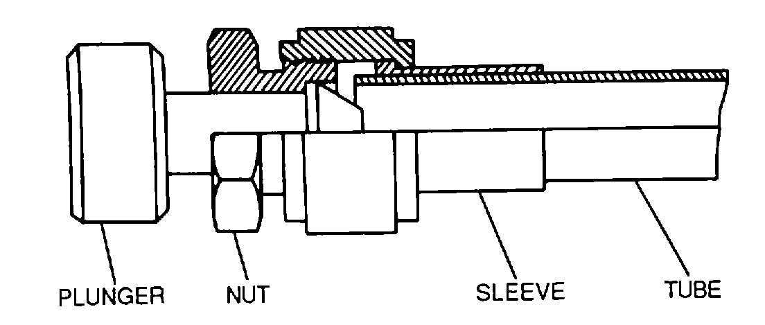
Figure 4-121. Individual Flaring Tool
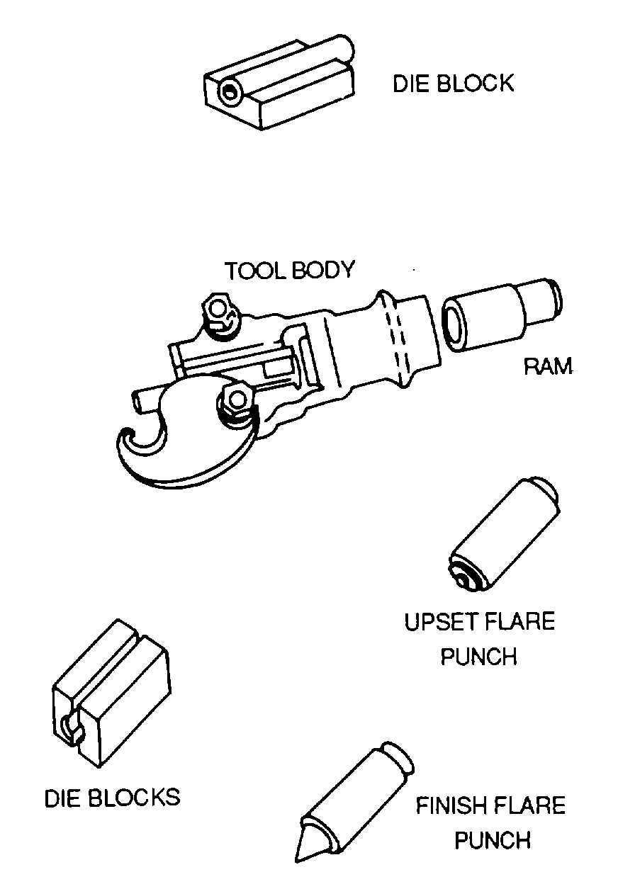
Figure 4-122. Double-Flaring Tool
b.
Use. The following paragraphs provide
procedures for flaring tubing using the flaring tools
described
above.
NOTE
Refer to TM 1-1500-204-23-2 for specific
flaring procedures and requirements. The
following
instructions
are
general
in
nature and are intended to illustrate the
operation of these tools.
(1)
Combination flaring tool. To flare a tube
using a combination flaring tool, proceed as follows:
(a)
Loosen the die block clamp screws
and open the die block.
(b)
Insert the tubing to be flared into the
die block. Allow 1/16 inch to extend above the die
block, and tighten the die block clamp screws.
(c)
Place flare cone over the end of the
tube.
(d)
If the flare cone is activated by a
screw, tighten it until the end of the tubing is forced into
the countersunk hole in the die block. If the tool has a
plunger, tap the plunger lightly with a hammer until the
metal assumes the shape of the countersunk hole.
NOTE
Rotate the plunger slightly after each
hammer blow to ensure a uniform flare.
(e)
When the desired flare is reached,
remove the flare cone from the tube.
(f)
Unscrew the die block clamp and
remove the tubing.
(g)
Inspect the flare for cracks or
breaks. If a crack or a break is detected, the tubing
must be cut and reflared.
(2)
Individual flaring tool. To flare a tube
using an individual flaring tool, proceed as follows:
(a)
Place the sleeve (MS20819) into
the nut (AN818) and screw the nut onto the tool.
(b)
Insert the tube through the sleeve.
(c)
Hold the tube and strike the head of
the plunger with a hammer.
NOTE
Rotate the plunger slightly after each
hammer blow to ensure a uniform flare.
(d)
Stop hammering when the flare
reaches the desired dimensions.
4-50