NAVAIR 01-1A-505-2
003 02
TO 00-25-255-1
Page 82
TM 1-1500-323-24-2
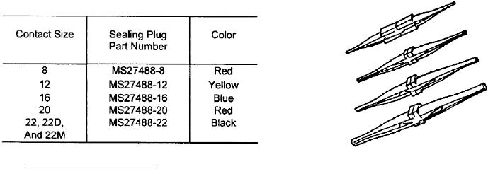
Table 30. Sealing Plug Selection
Figure 29. Insertion and Extraction Tools
164. CONNECTOR BUILD-UP. For new connector
build-up assemble tools required along with applicable
c.
Lay wire in groove of insertion tool colored
necessary contacts and applicable necessary wire and
tip. Slide contact into front of tool until properly
cable. Refer to applicable drawings or diagrams to
located and seated (Figure 30).
ensure correct build-up and wiring procedures. Refer
to the Table by Series to determine the proper tooling
d. Insert contacts using either the alternate row,
and contacts.
or center outward method.
165. WIRE DIAMETER BUILD-UP. In cases where the
(1) Alternate Row Method. Insert contact in
wire outside diameter does not fill the grommet sealing
one row at center, skip one row insert contacts repeat
holes, environment resistance will be severely
until all contacts are installed (Figure 31).
degraded. The wire diameter must be built up to
provide proper sealing prior to contact insertion.
(2) Center Outward Method. Insert center
contact largest letter or number first, insert others
a. Select proper heat shrinkable insulation
following pattern (Figure 32).
sleeving in accordance with SAE-AMS-DTL-23053.
b. Cut to length necessary to extend 1/4 inch
e.
Working from rear of connector hold tool with
contact at right angles to the grommet, place contact
beyond grommet.
into proper hole (Figure 33).
c.
Do not apply so as to cover crimp contact area.
f.
Keep contact and tool centered in hole, apply
smooth even pushing pressure until contact is seated.
d. Using proper reflector apply heat using
A faint audible snap may be heard when contact seats
HT-900B to shrink.
(Figure 34).
e.
Repeat above steps until diameter is built up
g. Withdraw tool only at right angle to grommet
to seal in the connector grommet.
face until completely free.
166. SEALING PLUGS. Sealing plugs are used where
h. Insert all wired contacts first, install unwired
unwired contacts are placed to maintain environmental
contacts in remaining holes.
resistance. Sealing plugs are sized according to contact
size (Table 30).
i.
Insert sealing plug behind each unwired
contact. Push sealing plug (large end first) until seated
167. CONTACT INSERTION. The following
(Figure 35).
procedure covers insertion of wired or unwired,
power, thermocouple, coaxial and twinax, contacts:
j.
Provide a moisture barrier and seal connector
in accordance with NAVAIR 01-1A-505-1, WP 026 00.
a. Assemble the contact and wire, crimp contact
in accordance with NAVAIR 01-1A-505-1, WP 013 00.
k.
Install backshell in accordance with WP 003 03.
b. Select insertion tool specified for contact size
(Figure 29).

