NAVAIR 01-1A-505-2
003 02
TO 00-25-255-1
Page 86
TM 1-1500-323-24-2
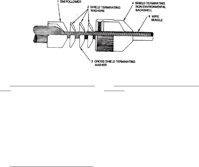
Figure 43. Feeding Wire Bundle Through Backshell
173. CONNECTOR REMOVAL AND INSTALLA-
177. MIL-C-29600
CONNECTOR
SYSTEM
TION. If the connector cannot be repaired or is severely
BUILD-UP.
damaged, perform the following:
178. CONTACT INSERTION. The following
a. Starting from the outside of damaged
procedure covers the insertion of wired and unwired
connector tag all wires and remove all contacts.
contacts for the MIL-C-29600 connector system:
b. When contact cannot be removed cut wire or
a. Select proper contact, tooling and strip
cable as close to connector as possible. Install new
dimensions from Table 31.
contact to wire (NAVAIR 01-1A-505-1, WP 013 00).
b. Assemble contact and wire in accordance with
c.
Install wires with crimped contacts from
NAVAlR 01-1A-505-1, WP 013 00.
damaged connector to a new connector.
c.
Select proper insertion tool from Table 31.
d. Seal connector in accordance with NAVAIR
01-1A-505-1, WP 026 00.
d. Feed wire bundle through backshell,
terminating washers, and follower (Figure 43).
174. FIXED CONTACT CONNECTOR BUILD-UP.
e.
Place wire in insertion tool groove and place
175. Connectors that are hermetically sealed or are
into position.
through-bulkheads have fixed contacts which are non-
removable with solder cup wire barrels. Wires are
f.
Pull wire back into insertion tool until contact
soldered to contacts in accordance with solder
shoulder seats against face of tool (Figure 44).
procedures NAVAIR 01-1A-505-1, WP 016 00.
g. Hold insertion tool perpendicular to grommet
176. REPAIR. The procedures for repair are in
and center contact in proper cavity (Figure 45).
accordance with standard maintenance practices and
solder procedures (NAVAIR 01-1A-505-1, WP 016 00).
h. Apply smooth, even pressure until a faint click
Seal the connector and provide for moisture barrier in
is heard or a solid stop is felt (Figure 46).
accordance with NAVAIR 01-1A-505-1, WP 026 00.
i.
Carefully remove insertion tool by pulling
back at a slight angle.
j.
Fill all unused cavities with unwired contacts.
k. Push sealing plugs, large end first, into
grommet until sealing plug bottoms (Figure 47).

