
NAVAIR 01-1A-505-2
008 02
TO 00-25-255-1
Page 24
TM 1-1500-323-24-2
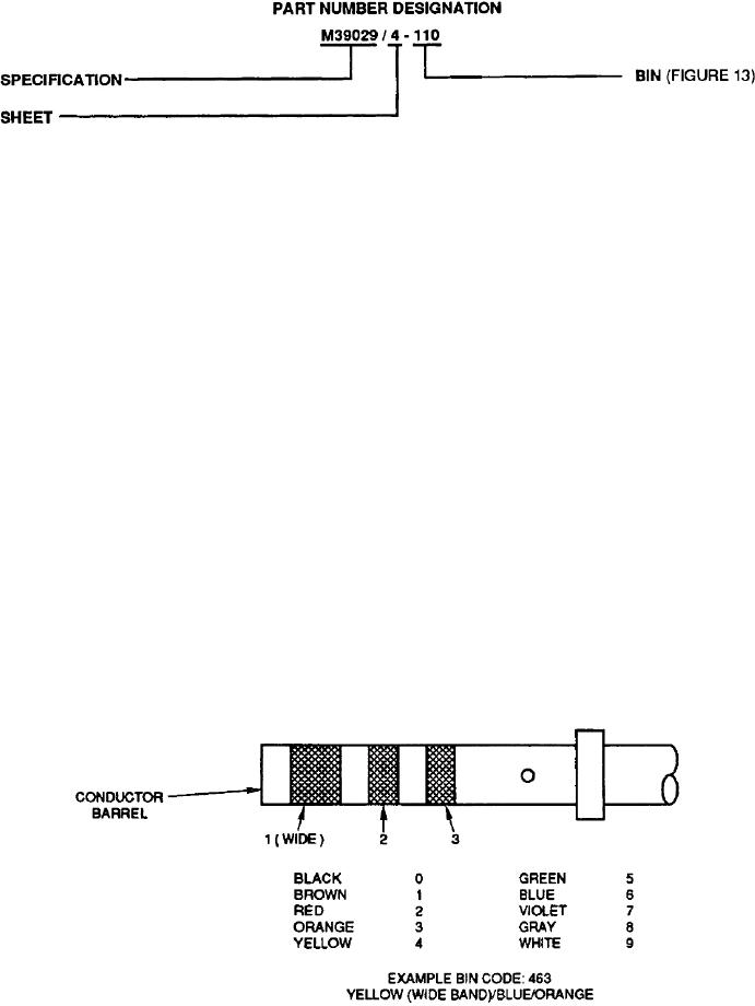
Figure 12. M39029/4 Part Number Breakdown
87. THERMOCOUPLE CONTACTS. Temperature
89. COAXIAL CONTACTS. When routing coaxial cable
sensing systems utilize two dissimilar metal conductors
through connectors, coaxial contacts are superior to
with matched lengths. When joined at the point
other coaxial cable shield termination methods. The
temperature will be sensed, a voltage difference
shield integrity is maintained across the contact body.
develops. This voltage is directly proportional to
The coaxial cable groups listed (Table 4) can be
temperature change. Thermocouple contacts listed
interconnected through MIL-C-26482 connector size 8
(Table 4) are either nickel-aluminum/silicon (formerly
and 12 contact cavities. Match the required contact size
alumel), nickel-chromium (formerly chromel), iron,
to connector application and cable group. When
copper, or copper-nickel alloy (formerly constantan).
crimping center contact for these cables, use crimp tool
Match the required size to connector application, wire
selector knob settings specified. Socket and pin contact
gage, and composition. Socket and pin contact part
part numbers are listed along with corresponding color
numbers are listed along with the corresponding color
bands. Socket coaxial contacts have a pin center contact.
bands.
Pin coaxial contacts have a socket center contact.
88. TOOLING. The procedure for attaching power
90. CABLE AND COAXIAL CONTACT ASSEMBLY.
contacts to a single conductor wire are the same for this
To assemble coaxial contacts to applicable cable identify
connector series. Select the proper tooling for the specific
cable by part number. Select proper tooling by contact
contact part number (Table 5) and refer to NAVAIR
size (Table 5).
01-1A-505-1, WP 013 00 for correct assembly and crimp
procedures.
91. BACKSHELL REMOVAL AND INSTALLATION.
For backshell removal and installation refer to
WP 008 03.
Figure 13. Basic Identification Number and Color Bands