
NAVAIR 01-1A-505-2
008 02
TO 00-25-255-1
Page 27
TM 1-1500-323-24-2
92. CONNECTOR BUILD-UP.
93. WIRE DIAMETER BUILD-UP. If wire outside
diameter is not large enough to fill wire sealing grommet
holes, build up wire outside diameter by applying heat
shrinkable insulating sleeving. This must be
accomplished prior to contact insertion.
94. WIRE STRIPPING. Strip wire in accordance with
following procedure.
a. Cut wire to proper length. Ensure enough wire
remains for adequate strain relief without leaving excess
slack.
b. Strip insulation from end (NAVAIR 01-1A-
505-1, WP 009 00). Select contact (Table 2 or 4).
95. CONTACT CRIMPING.
a.
Select crimp tool frame and positioner (Table 3
or 5).
b. Perform die closure check, install positioner,
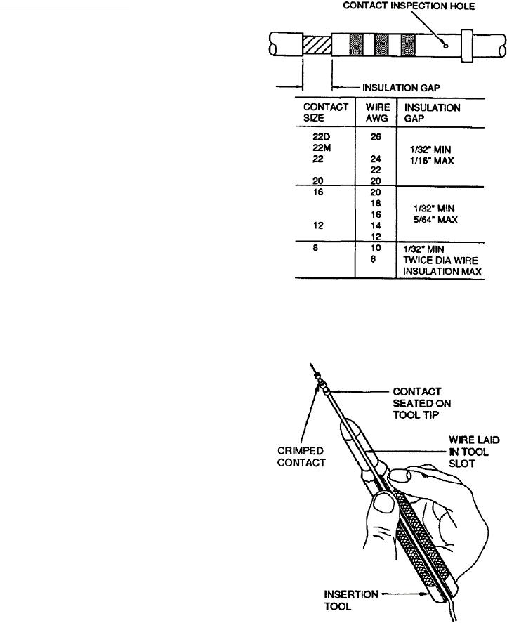
Figure 14. Insulation Gap
and set selector knob for gage of wire.
c.
Insert stripped wire into contact conductor
barrel. Ensure all wire strands are inside contact
conductor barrel and visible in contact inspection hole
(Figure 14).
d. If insulation gap is too large, trim conductor
as required. If insulation gap is too small, trim
insulation as required (NAVAIR 01-1A-505-1,
WP 009 00).
e.
Crimp contact to wire.
96. CONTACT INSERTION. Insert wired or unwired
contacts in accordance with following procedure:
a. Remove sealing plug and/or contact from
contact cavity (Paragraph 100).
b. Ensure wire or cable on contact is routed
through connector backshell.
c.
Select correct insertion tool (Table 3 or 5).
d. Place wire and contact assembly into colored
Figure 15. Inserting Contact into Insertion Tool
tip of insertion tool (Figure 15). Ensure tool tip is over
conductor barrel and butted against contact shoulder.