
NAVAIR 01-1A-505-2
011 02
TO 00-25-255-1
Page 4
TM 1-1500-323-24-2
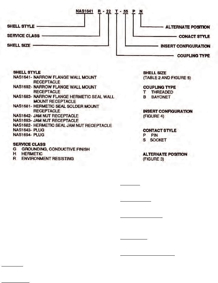
Figure 2. NAS1599 Threaded Coupled Part Number Breakdown
17. Shell Size. Shell size is indicated by a progressive
12. COUPLING. Connectors shall be capable of being
numbering system.
fully coupled and uncoupled without use of tools.
18. Coupling Type. The coupling type is a letter code,
13. POLARIZATION. Connectors are polarized as
denoting either threaded or bayonet.
denoted by their part numbers. This means that the
master keyway is rotated to prevent mis-mating of
19. Insert Configuration. The insert configuration is
similar connectors in a similar location. A plug with a
the insert arrangement by number and size of contacts
given polarization letter will mate with a receptacle
used.
with same letter. The inserts do not rotate, only the
keyway is rotated.
20. Contact Style. The contact style denotes the type of
contact.
14. PART NUMBER. The following paragraphs contain
the information necessary for proper selection and
21. Alternate Keyway Position. The alternate position
procurement of connector (Figure 2).
indicates insert polarization other than the normal
15. Shell Style. The shell style is denoted by the NAS
position (see Figure 3).
number and style of connector.
22. DESIGN AND CONSTRUCTION. Connectors and
16. Service Class. The service class is a letter code
accessories are designed and constructed to withstand
denoting environment resisting ability.
normal handling incidental to installation and
maintenance.